Thursday 15 December 2022

HP Elite Display and 50Hz


So I broke my primary display. For a while I suffered an old Benq display with 1920x1080 resolution, but then replaced it with this used cheap-ish 24" HP EliteDisplay E243i with a 1920x1200 resolution.

I was not initially too impressed with it. It is not completely flicker-free technology although the flickering is not nearly as obvious as the one used in the Benq. (And I barely noticed it there until it was pointed out to me.)

On the positive side, it is pleasing as an object, the frames are thin, doesn't shake excessively, pivoting is extremely easy and goes both directions. Connections are Displayport, HDMI and VGA.

But I probably wouldn't write about this without a happy accident: the display has 50Hz refresh rates. 

These only work for the 1920x1080, 1280x720 and 720x576 resolutions. In practice the 1280x720 is used if a 50Hz HDMI is plugged in.

This is desirable for various more or less "fake" retro applications and emulation, as the old computers tended to use 50Hz refresh rate in Europe. I had been actively searching for such a possibility, but gave up as apparently only TV displays have such rates.

For modern displays, having 50Hz input does not always mean the frame rate is 50Hz, as it could be simply some kind of auto-conversion to 60Hz. Also, horizontal frequencies matter. For example, the ZX Evolution computer VGA is quite picky and the display couldn't catch the signal.


Converted image

I first tried an old Composite-to-VGA box and got a very cruddy Commodore 64 image on the display. Despite the poor quality, the frame rate is rock solid, with no indication of stuttering or 50-60 conversion.


Changing to S-video, the image improved marginally.

The box also takes in Y-U-V, which likely would be the best option for this video converter, but the C64 signal doesn't split that way.

Sticking C64 Composite and Luma outputs into these inputs produced a rather stable and crisp, but wrongly colored, striped image. Don't try at home.


Emulators and other boxes

Even with 50Hz, this display will never be on par with a CRT. The most egregious difference is of course the screen shape. Yes, the monitor can be told to do 4:3, which is a bonus, but it won't take the physical dimensions away.

I tried some emulators and the various HDMI-outputting retro gear I have around. This isn't a review of these platforms, just my experiences with the display and while I'm at it, notes on the Arduino joystick adapter.


UAE

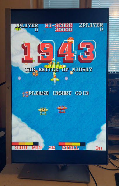
Amiga emulator on Linux. The emulator is surprisingly smooth, and tearless after checking on the vsync tick box. But for some software, the frame rate is not endlessly rock solid. Already looking at the Giana Sisters intro screen I could on occasion see the scroll hiccup a frame. 

But during games and the few demos I tested, I could not really see any problems at all. I guess it partly depends on how the sync is achieved at the "Amiga" end too.

The interlaced Giana Sisters intro screen does not "interlace", and on occasions the lines are displayed in the wrong order.

Using the Arduino adapter, I can play games with the Tac-2 joystick, which is a bonus.


Amiga Mini

Yes, this commercial game console works rather fine and can be set to 50Hz mode. 

The interlaced Giana Sisters intro screen is displayed correctly. The screen scaling options are not very sophisticated, so the screen can end up either small-ish in the center or a big screen with scaling artefacts when scrolling.

The Arduino adapter doesn't work here, so I have to use either the supplied gamepad or the Joystick from The C64. Neither are especially good.


Vice

Commodore 64 Emulator on Linux. Vice adapts to 50Hz but on my Linux/compositor the emulator doesn't quite achieve smooth sync. No clue why and there are really no further options in the GUI at least.

C64 is not pure 50Hz so there might be a systematic hiccup here and there, but at times I felt Vice hiccuping a little more than I'd expect. I am also wondering if the emulator creators really bothered to enforce the slight difference, but perhaps cycle exact is cycle exact.

The Arduino joystick adapter works here nicely, though.


C64 BMC

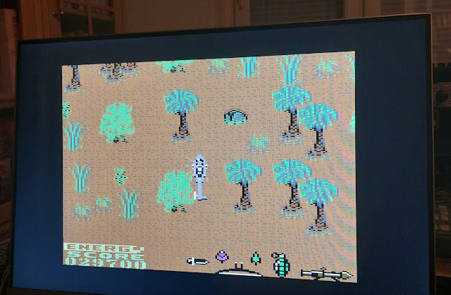
A Raspberry Pi -based "bare metal" emulator with HDMI out. It needed some fiddling with parameters before I could get an integer-based display scaling, fortunately these can be done from the BMC menu itself.

This was not altogether satisfying, as to get a huge screen with integer scaling, the borders had to be sacrificed. If borders are included, then the usable screen area becomes rather small. In many games it matters little as the borders are often black.

I have to say I'm not exactly sure why the rest of the screen can't be used, there may be still something to explore.
Aahh...

As I've modded the BMC to have original C64C keyboard and a 9-pin joystick port, the experience is quite good and I can directly use my Tac-2.


The C64 Maxi

The commercial hardware emulator. With only HDMI out, no doubt it can do the job. There's also a selection between 50 and 60Hz modes, but as I recall this had to be done at the boot.

Selecting the "pixel perfect" mode I get a pleasant enough, unnaturally crisp HDMI C64 image with borders, something that was a little tricky to get out of BMC.

What is less pleasant is that I'm apparently stuck with the joystick that came with The C64, the Arduino Joystick adapter could not be used here.

Apparently to have more HID devices accepted by The C64, there's a workaround but I'm not yet prepared to go there. Still, it's promising that this problem has a solution too.

I get a good image more easily than with the BMC, but the BMC has better joystick options and is possibly a little less laggy.


The Outcome

So, all in all I think the Linux can do UAE rather well, and for more frame-accurate C64 emulation I have two choices with this display.
Monday 12 December 2022

Another time, another Fostex


Yes, the "red one".

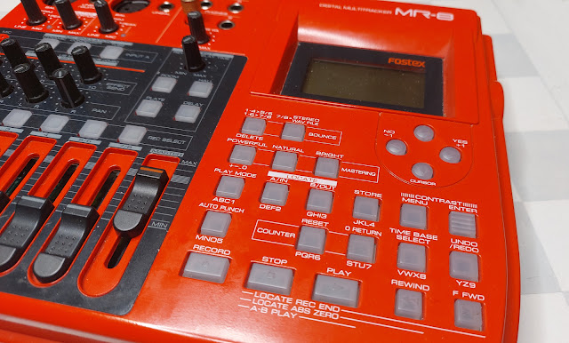
I did once discuss a broken Fostex 4-track tape recorder, which I never really properly repaired. I got a good impression of the Fostex brand and when this striking-looking MR-8 digital recorder was available on a net auction, I blindly hurried to get it. This already some 5 years ago I think.

After the initial excitement of having a multi-tracker strongly influenced by the 4-tracker tape workflow, I felt it was too slow and limited and the box mostly spent time at the back of a shelf. Besides, calling it an 8-tracker is really a stretch. You can only record two inputs at a time, and only four of the tracks behave individually. The 4 other tracks are stereo "bounce" pairs 5/6 and 7/8.

The MR-8 is from around 2003-2004 after all, at a time when a cheap digital recorder became a possibility but the concept was still somewhat marred by tiny memory space, slow USB and card speeds.

Now, for one reason or another I felt it might find at least a temporary place on my desk. There's something fun about listening a recording without even turning on the computer, and on occasions learning to be slower with your methods might even be helpful.


Upgrades

One motive to dig this out was that I found out there are firmware updates. I did the 1.21 upgrade and saw this would allow me to use a 2GB compact flash card instead of the 512MB one installed. Fostex had also supplied a list of cards proven to work, which was pretty nice of them. I ordered one from eBay, a Sandisk brand 2GB card. This would bump the 48 minutes of 4-track recording into a maximum of 188 minutes.

A repeat of the firmware update instructions:

After finding the MR8V121.zip from Fostex website, unzip the file within, and use the USB function of the MR-8 to copy it over to the compact flash. (The MR-8 appears as a sort of memory stick, if the USB mode is on) After this has been done, shut down the MR-8. Then hold STOP and turn the MR-8 on again. Now the Fostex should prompt you with something like "version up", and as usual, you have to confirm it with RECORD+YES. Wait for a while, and after the upgrade is done the Fostex should be again shut down. After turning it on, you should see the version is now 1.21.

A Fostex document suggests turning the "EXTEND" mode on in the Fostex before doing the upgrade, but this might be required if the card has seen some use. My card was nearly empty, and I guess there were no problems even if I didn't turn the mode on.

After upgrading there is an option for auto-delete of undo space, but I left this off for now.

After inserting a new 2.0 Gigabyte Compact Flash card and turning the power on, the Fostex offers to format the card. After this procedure there is more than 6 hours of mono recording time in the normal mode. 

The space use depends on the amount of tracks and how much undo buffer is in use. As should be, the recorder does not waste extra space when not needed. So, if you first record a few minutes to tracks 1 and 2, and then record a few snippets in the middle of track 3, these will only take a tiny amount of memory and not a full track.


Learning to fly

I became motivated to study the device and the manuals a little more, finding some neat functions I had been so far unaware of. The manual, despite having some typos and tiny language problems, is extremely clear and well illustrated.

As an example, I was originally unimpressed with the slow export procedure. You can't simply copy your work in progress using the USB connection. The tracks 7/8 are exported into a specific WAV stereo file, which in turn can be copied over the USB. Creating the 7/8 track seemed to require the re-recording of the tracks using "bounce" function.

But now I learned I don't really need to re-record to 7/8 in real time in order to export them to WAV, as I can simply "copy" tracks 1-2 to 7-8 internally, which is much faster. Assuming all the material is in tracks 1-2, that is! Then again, if I'm using all tracks I could choose to export tracks 3 and 4 to 7/8 too and combine the audio at the PC end.

Anyway, this track-copy function helped me try out different recording parameters and seeing the results rapidly on the Linux side. I also found out that most of the track functions work not only on single track, but on the 1/2, 3/4, 5/6 and 7/8 pairs which makes these tools more useful.

Also, the part copy and erase functions made more sense once I used the internal clock to synchronize a sequenced recording. This way, the recording can be revisited in Bar/Beat timing and not in seconds. I'll tell more about this below.

The sync also could help record tracks separately with accurate timing. For example, record one song element to tracks 1/2 first, then another to 3/4. An optional audible metronome click helps live play.

Using the inertial rewind and forward buttons together with the unresponsive STOP is still quirky. I could have used the good honest cursor keys to step between bars.

Things like the on-board effects processor and mic/amp simulations are perhaps better ignored, as they are not very functional and some of them are simply on-off without any parameters. It looks like everything in the device is geared towards making a simple demo for a performance that might include a guitarist and a vocalist.

For the hell of it, I also tried XLR cables for inputting balanced audio from the mixer, although with the distance of 1 meter it should matter very little what kind of cables I'm using. The XLRs ought to be used for microphones really. But in contrast with instrument cables, I seemed to need less TRIM for Input A and B to get the same volume level, which kind of sounds promising? My ears could not really discern any difference in results, though.

Opening the box

I also felt an urge to look inside the box, as some of the buttons were a little unresponsive. The STOP button and the STORE button have to be pressed hard to make them work. Yet it was clear the switch below the button "clicks" in a tactile way.

Some sawdust particles had got between the LCD and the plastic cover, and this irritated me as the screen's not that big anyway.

Pull out the faders first. The knobs do not need to be removed.

Do not remove the "foot" screws and the "battery compartment" screws. Screws near "Digital Out" and possibly MIDI, do not need to be removed either, but I did take out the latter. (Edit: These do not need to be removed.)

There are screws at the bottom and back that need to be taken out. The three bottom screws near to the back connect to a metal plate that needs to be detached later. These screws are somewhat longer than the other. (When putting these three back, put them loosely in before tightening them fully, otherwise one of the holes may be mismatched and it will be difficult to fit.)

Then the red cover should pull out together with the LCD and the fader/button unit. After disconnecting the mic leads and the two ribbons, the parts can be pulled out entirely. I found it easier to unscrew the mic rather than try to disconnect it from the circuit board.

Then, more screws need to be taken out to detach the LCD/fader unit from the plastic cover. There's also a protective "silver cardboard" which probably does little or nothing to remove interference.

After cleaning any visible dirt and putting it all back together, the STOP and STORE button did not become markedly more responsive. Possibly the switches have become worn out. I did manage to clean the space between the LCD and the transparent cover, so there are no longer any particles there.

Possibly, to repair the buttons I'd need to replace the microswitches on the circuit board. They did not appear in any way loose, and the one-piece plastic contraption containing all buttons didn't look damaged.

5.2.2023 Edit: I took a closer look, and re-soldered the tactile switch connections while pushing the switches closer to the board from the topside. This improved the connection and the STOP/STORE buttons now work with lighter touch. The switches are 6.2x6.2mm with top measured varying at 4-4.5mm because of the way they had been soldered in. With only two pins as the poles it would not be surprising they might come loose easily.

MIDI clock-based recording

The Fostex has a MIDI out port, a feature I had not previously used. I recall this caused some initial confusion in me, why does a recorder have a MIDI out port? But it's actually rather obvious. The port transmits the MIDI clock to a sequencer and it is possible to make timed recordings this way.

A song can have a tempo and time signature map, so the Fostex is not limited to one overall speed or time signature. After making these selections and recording a synced track, it's possible to switch over to the Bar/Beats notation instead of the hours/minutes/seconds timing.

There are even two kinds of sync methods, the simpler MIDI clock and the SMPTE/MTC. I used the simple clock, and it looks like to me for recording a complete song it should be sufficient and uses far less MIDI bandwidth.

The simple MIDI clock sends start/stop/continue signals and a continuous "click", all using single-byte signals. 0xFA for start, 0xF8 click, 0xFB is continue and 0xFC is for stop. Other MIDI message contents are always seven-bit, so even if a click arrived mid-message, it shouldn't be difficult to parse. 

For a 4/4 time signature, the click byte is sent 24 times for each quarter note, giving a resolution of 96 for one beat. 

Frankly, the alternative MTC format looked rather complex, as it sends portions of the time stamp little by little. The sequencer may even need to interpolate these and "lock on" to the signal. The plus side is that it becomes possible to start the playback from any location. In the simple clock mode the Fostex doesn't send the SysEx for song position. On the topic of MIDI timings I used Francis Rumsey's book Midi Systems & Control, 2nd edition, from 1994.

When the START signal is sent (by pressing Play on Fostex), Fostex can be told to wait for a couple of empty bars before the click signal begins to roll. For my sequencer, this handily means the MIDI data can be rendered and linearized for playback, which can take a tiny moment. As the sequencer receives the click, the virtual playhead is advanced and MIDI out signals are sent to instruments.

After pressing STOP on the Fostex, the click is no longer sent and the Stop byte is send via MIDI. This can tell the sequencer to stop worrying about the incoming clock, or something.

One obvious use for this when importing the Fostex-exported WAV to a Sequencer/DAW, here for example Qtractor. After setting the tempo I have the track laid out according to plan.

Working with the bar/beat model, it's also possible to make better use of the Fostex Part erase/copy/paste functions. Usually the A and B positions are meant for working on a song position, such as re-recording a portion with multiple takes. Here the A->B positions signifies an area to be operated on a single track, and they can "snap" to beat resolution. This way I could remove a few bars out from a track, or even extend the song further by copying more material to the end.

Also, I recorded separately a bassline to tracks 1/2 and percussion/other stuff to 3/4, from the same song, and the result sounded pretty accurate to me.

So in theory, a song can be constructed using already recorded short elements. This might be silly in this time and age, but as a zen exercise in patience, it might just spur someone's creativity.

Wednesday 16 November 2022

Korg Nu:Tekt NTS-1 ma:SSaKred

128mm wide, 78mm deep, 17mm high (excluding controls)

I got this about 100€ tiny brick of a synth, Korg NTS-1, or Nu:tekt. You build the case yourself and it has that rugged circuit board aesthetic. There's also promises of customization, both in hardware and software.

So, is this the Arduino of synths? Well, yes and no.

Yes, because it can be modified, and there are pins for accessing inputs and outputs. Yes, because it is very tiny. No, because the software architecture uses uploaded modules and it is not as "open" as an Arduino is. Yes, because you can also compile your own modules. No, because there's not a huge row of pins to access every meaningful aspect of the synth.

NTS-1 is not unique, there are several build-yourself-a-synth models around. The self-building aspect is at least partly a gimmick. But it's a nice product idea, potentially bringing the cost down a little. NTS-1 was really simple to put together with the instructions, no soldering or extra tools were needed. I used a somewhat larger screwdriver than the one supplied.

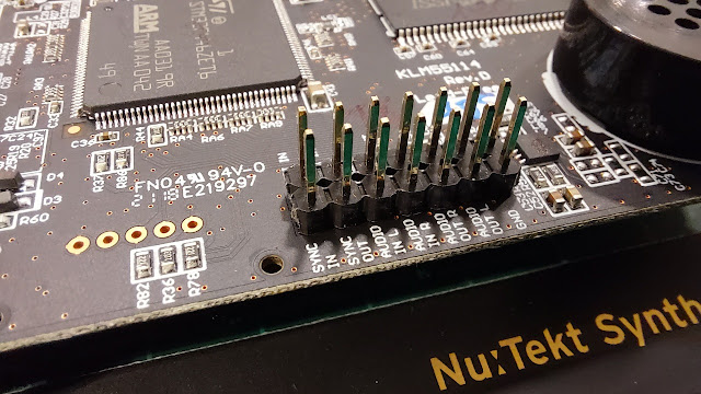
There are a few pins and soldering points that can be used to expand the synth. MIDI, audio and the sync clock are present both as ports and on-board connections. The real changes to the sounds and functionalities are done through uploading different modules.

I had somehow thought I could also use Nu:tekt as a MIDI-controlled adjustable filter, something you don't see that often. To my disappointment the audio-in is diverted to after the filter, and you can only select whether you want mod/delay/reverb affect your audio input.

But this is not the end. It is possible to upload new oscillators, modulators, delays and reverbs via the Librarian app. So I could add third party filters from DirtBoxSynth just to fix my grievance. This added some ~€10 to the cost of this device. Whether these filters are as good as the fixed ones, I can't vouch for.

The Librarian app

I also learned the architecture is shared between Korg Prologue and Minilogue, which means there's a wider market for these modules. Not all modules might be applicable for the context of NTS-1.

The Librarian app is only available for Mac and Windows, but fortunately it worked well in my 2012 Mac. A glance at the coding side makes me feel it wouldn't be impossible to compile my own effect (there are tutorials and examples) but it's doubtful I can do the math for anything useful.

Apparently an imported module only fits a particular category, so you cannot upload "bitcrusher" to Delays or Reverbs, it has to go to Mods. If so, I cannot choose to chain the DirtBoxSynth filters with the bitcrusher, it's either/or, because both go to Mods.

Ok, let's look at the more physical side of things.

The headphone is at the other side

The boards and the elements are meant for constructing the default box, so it's not a set of legos. Still, the process is nearly reversible and you are not stuck with the box you built. It should be easy to remove one of the four 1mm side panels, and replace them with your own, for example.

About that "nearly reversible". Because the instructions said so, I cut off the four screw holders from the board corners. As far as I see now they do not need to be removed when making the standard case. So, be aware when building the case you are making a permanent change! 

The controls are integrated to the top panel, which doesn't look too simple. The ribbon keyboard input connector looks a little tricky, attaching an alternative keyboard is probably not going through that route. Either find out what the pins between the top/bottom do, or use MIDI.

Header pins and four screws keep to cover in place.

The NTS-1 has no patch storage, but this is a minor inconvenience, considering all parameters can be transmitted via MIDI Control Change messages. There are Oscillator, Filter and Envelope types, with A and B parameters for each. On top of that you can have Mod, Delay, Reverb, LFO and Tremolo. There is also a rather full-featured Arpeggiator.

Like all the audio and sync ports, the MIDI port is 3,5mm one, with tip-ring-sleeve arrangement. So one of the first customization decisions might be whether you need an adapter cable (be aware of Type A and Type B) or build your own full-size MIDI port using the solder points inside. This is what I did, not long after putting the thing together.

The USB also connects the device to your computer as a visible MIDI device, so whether you even want to use the MIDI port for connecting is up to you.

Adding the full-size MIDI port

The box was even easier to open than to put together. The front or the rear panel needs to be removed before the circuit board can be lifted out.

After removing the board it is easy to access the through-holes for MIDI, AUDIO and SYNC. Note that 5v and 3.3v can be drawn from here too.


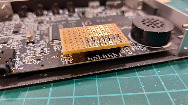
I soldered in a header strip for testing. Then I realized the jumper cable heads would not fit under the cover, so I instead added a tiny layer of prototyping board. A ribbon connector might have been helpful here.

This way I can solder/de-solder wires should I need to change them. I wouldn't want to heat the actual Nu:Tekt board too many times.

The MIDI in "tip", "ring" and GND("Sleeve") need to be connected to a MIDI DIN-style connector.

I soldered the wires on the proto pads, as it was too tricky to nudge them from the underside after the board had been fit to place. There's one more layer of that header strip keeping the board higher.

I could have soldered the wires beforehand from the more correct direction, though.

Internally, MIDI channels are 0-15, in hex 0-F, whereas software and documentation refers to them as 1-16. This discrepancy sometimes rears its head and creates confusion, but I've become used to it.

How to change the MIDI channel? Consult the manual. Plug in the Korg and press REVERB at the same time, you get to the parameter menu. Find the parameter CHL with the Type knob and change them using the B knob. Push ARP to store the parameter to the internal memory.


Wednesday 2 November 2022

Zoo 2022

The largest Finnish Commodore 64 demoscene party, Zoo Party, took place in Orivesi campus 28-30th of October, 2022. Although 2021 saw the mostly-online "World Wide Zoo" event, there really hasn't been a proper Zoo party since 2019.

Given the somewhat lacklustre Assembly 2022, I had mixed expectations. Have sceners been sharpening their weapons and ready to release their pent-up creativity in full pressure? Or do we get to see a small batch of zombified entries?

The Party Bus arrangement made it easy to join from Helsinki to the party location somewhat east of Tampere. A train would have worked well too. It was already known there would be rather many participants, and the bus was quite full. As the evening turned from the depressing grey to night-time darkness, the atmosphere began to build up.

It was nice to see the campus setting had far more space than that hotel at Akaa, and the accommodation was very good.

At this point I have to say the Akaa hotel (2013-2019) had a nice atmosphere and the mezzanine added some "dimension" to the space. Yes, having a sports hall as the main party space just doesn't have that Kaurismäki/David Lynch feel that the tiny hotel had.

But still I'd say overall this location wins and when it comes to sitting in front of your C64 and enjoying the party audiovisuals, the architecture doesn't matter that much. Also, in Akaa the bar in the party hall was something of a mixed blessing.

The responsibility of feeding, when carried by the party organizers, was unclear at times. But as there was an arrangement with the house kitchen, the breakfast and supper were professional. As a welcome bonus, Wide Load additionally provided hot dogs, if you were there at the right time. Now there were no pre-bought beer tokens, and beer did flow freely, up to the rumored 700 liters in total.

Entering the foyer, one was greeted with arcade game selection from Reprocade: Wizard of Wor, Crystal Castles, Tempest and Klax. I was able to try each one quickly during the party. 

The merchandise was there too, notably the obligatory Zoo T-shirts and the new Finnsids II SID album. The exhibition of Game Boy art, displayed on real Game Boys, was an additional curiosity. That's a rather hardcore display format for graphics! The entrance space also hosted the flea market on Saturday, and you could also upgrade your C64 with diverse gear. I bought a replacement PSU and I'll discuss that in another blog post.

As usual, there were a couple of talks. One was Miha Rinne, a long time game industry professional and the author of the graphic novel Journeys in Game Industry (Matkailua Pelialalla). He told of resurrecting a very old C64 game project called Undead, with side-scrolling zombie smashing fun. The completely new version will re-use the concept of that old game with new graphics and sound. Interestingly for me, at least some of the background graphics had been mocked up with Multipaint.

Lasse Öörni AKA Cadaver, of the Goattracker fame, is of course also known for the C64 games such as Metal Warrior and Hessian. He showed interesting details about the tools and cross-development environments he had built for game development.

Both of the presentations seemed to highlight the importance of self-made (or in-house) tools that can be even particular to one game project. In Rinne's case this approach enables the designer to build game content without having to become entangled with the coding. In contrast, Öörni, coding everything on his own, could explore the possibilities of memory- and speed optimized level storage through creating his own map editors.

The musical acts were there too, such as Terracuda (Deetsay/Tero and Barracuda) and 8-bits high. I would enjoy these shows but somehow tend to miss them as there's either something else to do or I'm already asleep. At least 8-bits high are gigging here and there, so you don't have to go to a demoparty to hear them.

Off to the compos.

Zoo Kids was a fun competition for kids, let's say the daughters and sons of middle-aged sceners. The works were submitted remotely (I doubt many would bring their kids to Zoo) And it was nice to see Multipaint used for this purpose too.

For the SID music compo, my seat wasn't probably at the best place so I grew a little weary of the fat kick sounds and had to move farther away. After the party, I enjoyed some of the winning works at the comfort of my home. To me SIDs are best enjoyed in small quantities, and Zoo often has dozens of pieces!

In the graphics compo many reported that Multipaint was part of their tool palette, which was a pleasant surprise. Clearly, over the the years the software has grown steadily in popularity to the point that a number of people came to comment on the software, often with some development ideas.

Cartoonzone

I worked on my compo entry image for quite a while and to me Cartoonzone represents quite well the kind of picture I really want to do currently. It combines Multipaint work with modest sprite multiplexing. Unfortunately it did not do especially well at the compo, I hoped it would land in the top 10.

The more jokey PETSCII, Samantha Fox Strip Poker, actually did reach position 6. Overall the compo had a solid selection of great works, but PETSCII perhaps isn't able to impress me so much as it did back in 2013-2015. Perhaps Peak PETSCII has been reached?

Samantha Fox Strip Poker

Earlier in the autumn, I still had some hopes to contributing to the game compo, but these hopes withered as the deadline loomed. Especially the last few weeks before the party were not conducive to finishing a game project, doing the graphics entry was enough. Although the number of entries was not high, the quality was pretty good. Perhaps not a surprise the more humorous and "demoscene-esque" of the games won (Burger Ninja) rather than the one I felt had a solid game concept (Knight Trap).

And let's not confuse this Game Making compo with the games compos. Lumberjack was surprisingly exciting to follow as the players one-upped in what appeared to be quite an intense and stressful game.

Cosmic Convoy

The disc cover compo doesn't have that many entries, so it wasn't impossible to get into 3rd position. It's a compo I have often wanted to contribute to. But I rarely get into the mood before the party, and when at the party place the time is often spent on other things. This time it was possible and there were some spots where I could advance the drawing while eating and listening to others.

I'm a little confused why Party Feature and Wild Compo need to exist as separate categories, but I guess it's more comfortable to submit to Feature things that would be at the party in any case, such as logo banners. The Wild I guess is still reserved for the video works and alternate computer platforms.

Oh, and by the way why is it ok to play SIDs on top of graphics entries, but not ok to show graphics while SIDs are playing?

The demo compo was so late and we knew there would be a huge number of long-ish demos, so frankly I had a nap during it. But from what I saw the quality and number of the best demos was really high.

So, yes, to answer my question, it looks like Zoo and the C64 sceners were back in full force.

Zoo 2022:  5/5, I'd take part again.

Friday 21 October 2022

Quickshot Flight Grip

I found this cheap Quickshot Flight Grip aka Quickshot Handlebar aka TecToy Asa. Designated QS-129N, I guess N is for Nintendo. Yes, sadly this is a NES controller, so I can't get instant gratification with playing Afterburner on the C64. Even my only NES machine is a clone that takes in a different kind of connector.

The shape is just irresistible, but it is clear the design is a gimmick and does not work well as a general gamepad.

It's worth noting the idea is not that far from the Playstation 1 controller that became the nearly universal starting point for all subsequent gamepads. It's just the grips are too spreadeagled and the d-pad and buttons are too near the centre. Bonus points for having the B-button as a "shoulder" button here, too.

Unlike the much later Gravis Destroyer Tilt, this Quickshot is NOT a motion-sensor gamepad. And given my experiences with the Tilt, it's perhaps all the better for that.

The size is for smaller hands, but that's not the biggest problem. The d-pad sounds and feels a little lifeless, and sometimes I think the B-button would be better as the principal fire button.

Looking at this from an alternative angle, I can see myself holding it like a boomerang (Batarang?) although then I'm more clearly limited to either the d-pad or the two buttons.


A look inside

Old electronics look often more crude than the outside suggests. The Quickshot is built more like a toy than an object for hardy use.

But it is a clean design. A bunch of screws keeps the outer case together. The circuit board in turn has a couple of tiny screws, after loosing them the whole thing begins to fall apart.

The buttons at front are on a separate board that must be identical to the Atari version of this controller. The NES-relevant stuff is on the central board.

The cable is tied and held fast in a tight curve, and a wide screw helps keep it there. Not sure this is better than having a "stopper" in the cable itself, but it looks firm enough. This also helps me attach whatever cable I need to.

Looking from the other side, the circuit board was quite dirty and I wonder if this would even work without some adjustments.

The main board had the notation "24 Aug 1990" in it, and the tiny board with the d-pad and fire button has the text "Spectravideo 1989".


The Conversion

I felt it should be easy to "downgrade" the gamepad to work in the Atari/Kempston style, as it only requires me to remove the electronics in between and add a different cable.

The first idea was to replace the main circuit board with my own, so I could store the original relatively intact. At the same time I could get to do easy and enjoyable protoboard work.

However, the autofire and select/start buttons require some corresponding physical parts even if they are not meant to work. It is better to keep the original board in place and simply remove the existing connections and replace them with my own.

The only really new thing needed was the cable and 9-pin connector to replace the NES-style connector.

This turned out to be a problem as I didn't have a worse joystick to borrow the cable from!

So, I ordered a lot of four broken joysticks from an auction. I got a possibly recoverable TAC-2 (the most valuable thing in the lot) and another Quickshot brand joystick I might spare. But importantly for my project, a couple of crappy non-brand sticks which I could cannibalize for parts, such as joystick cables.

I de-soldered the ribbon connector and soldered in single wires, which in turn were soldered to the joystick cable ends. The cable had a rubbery stopper which I had to whittle off before I could fit it through the opening in the Flight Grip case.


In the above image I marked the connector wires 1-7.

1: GND
2: Right
3: Left
4: Down
5: Up
6: Fire
7: GND for fire


Testing

I played some games on the emulator through the Arduino adapter box.

Buck Rogers was quite fine as long as I was only turning the ship left and right and firing. When the ship needed to go up and down, it felt far more clumsy.

Buggy Boy worked surprisingly well, as it's also a sort of left-right game. I need to push constantly upwards though and this proved to be a little taxing for the old thumb.

With Stunt Car Racer I experienced first genuine confusion. The acceleration is no longer about pushing up constantly, but has to be managed together with delicate left/right controls. Diagonals are a stretch and I performed considerably poorer than I do these days with a Tac-2.

I also kept missing the 2nd button function, but the question is, what should it do? Replicate fire button? Or replicate Up direction, to give an easier way to accelerate? Hmmm....

Blue Max is one game where I felt a controller like this could be fun. But I'd be lying if I said the Flight Grip delivered here. Blue Max controls are a quirky to begin with and the poor diagonals offered by the controller did not help much.


I also played a couple of games where I expected the controller wouldn't be good at all.

The Great Giana Sisters was not as bad as I expected, but it needs a more accurate controller. It might help to have the second button to be the "Jump" button, so perhaps I'll indeed wire it to "up" and try again.

In Saboteur!, a lot of the movement is left-right only so it was rather good for those portions. However I also have to reach those ladders accurately and this is where the controller failed me and I couldn't bear to play much more.

The controller is a better fit for "3D" games with relatively simple controls. So I wouldn't condemn the Flight Grip concept entirely, it's very clearly not meant to work for all games. If only the buttons and diagonals were more crisp and precise.

Oh, I nearly forgot. I meant to play Afterburner. The game is so atrociously unresponsive it's hard to put the blame on the controller.

I'll get back to this if I solder the 2nd button.

Monday 17 October 2022

Extenders

It's not worth having a bike or electric kickbike, without also having something to nerd about constantly.

As already mentioned before, I added a handlebar extender that enabled me to shorten the handlebar a little and still place the display to a comfortable position.

The extender has served well, but did not in itself help attaching a phone.

I saw this Wave Bike Clip and bought it off the shelf. Now this might be one of the crap and cheap solutions before I eventually find out I have to buy a Ram Mount anyway.

For me there were two main reasons for getting the phone holder.

First is the idea of having a map more easily accessible, which was one of the problems with the 28km planned journey I had. Stopping to dig out the camera out of the pocket every now and then was a nuisance.

I probably wouldn't even keep the map constantly on, it would be too much of a distraction. But it would certainly be easier to visit the map.

The second reason is to check the speedometer against a GPS-based speedometer app on the phone. This I only needed to do once, really. I confirmed the built-in speedometer is adequate and calibrated correctly. (It can be re-calibrated)

Given this accuracy, strangely enough the internal odometer is not very precise, at least compared to Google Earth. However this would also require more reference points, can I even trust Google Earth?

The Wave Bike Clip is in the middle, in closed position.

Filming video might be one possibility, but I'm not currently that interested in it and also suspect it would be really shaky.

I tried various ways of attaching this phone holder, which unlike the first extender only really fits to the actual 22mm handlebar and not the thicker bolts.

At one point the vertical stem looked like a better place than the crowded handlebar, but the gimbal couldn't provide an angle to do this well.

So, after trying different angles, I just attached the phone holder to the extender like I did at first.

There's also the issue that the collapsed package can also increase in size with these extenders.

The holder is quite shaky even on smooth pavement, and I kept fearing the phone might fall off, which I guess is unlikely.

The shaking may be because I have bashed together an extender on another extender, but it also made me appreciate how sturdy the first extender is.

The phone buttons are a small annoyance, of course they are exactly in the place that prevents me from centering the phone better.


Wednesday 5 October 2022

8-bit joystick adapter using Arduino

One day, I was looking for a 9-pin joystick ("Atari" or "Kempston") to modern PC adapter. After some disappointments, I googled for a comparable DIY Arduino project and found what I wanted from here:

https://hackaday.io/project/9552-digital-joystick-8-bit-to-usb-adapter

There isn't anything to code, as the functioning joystick examples are already supplied with the library. But as the instructions are a little on the short side I thought I'd add my experiences.

Firstly, the Arduino I had installed from the Linux repository was too old. Most of my time was wasted trying to get the library to work, whereas if I'd just downloaded the latest IDE, I could have added the library very easily.

One way to do this is to download the library as a zip, then use the Add .ZIP library function from the Arduino IDE menu. It's possible the IDE may need to be re-run. If the library has been installed, the GamepadExample can be selected from the File -> Examples -> Joystick submenu.

Not just any Arduino board can do this. Arduino Micro and Leonardo are seen as HID devices, so they can pretend to be joysticks, mice and keyboards depending on what you tell them to do. I had to buy an Arduino Micro to even try this.

ArcadeStickExample may sound attractive, but it requires an Arduino Micro Pro instead! Obviously a single-button arcade style joystick could work here.

The hackaday page isn't very explicit about which wires to connect to which pins, although the GamepadExample.ino will give some pointers.

Adapter port view pins:

 1 - Up to Arduino digital pin 2
 2 - Down to Arduino digital pin 4
 3 - Left to Arduino digital pin 5
 4 - Right to Arduino digital pin 3
 5 - Not Connected
 6 - Fire to Arduino digital pin 6
 7 - 5V (Not Connected)
 8 - GND to Arduino GND
 9 - Not Connected

I'm unsure of connecting the 5V to Arduino 5V, it looks like it was enough to connect the ground (GND).

It's also possible to have multiple joysticks, but I don't need that now.

Quick and unscientific lag-test: On Vice 64 I tried Buck Rogers, Commando, Decathlon, Giana Sisters, H.E.R.O. and Stunt Car Racer and Giana Sisters (again) on Amiga emulator.

With some of the more crisp C64 games I could perhaps see tiny bit of lag but not more than Raspi BMC64 or The 64 Mini/Maxi. All within sensible limits to me, and possibly not even because of the adapter really. Playing 50hz games on 60hz display is all kinds of wrong to begin with, anyway. Stunt Car Racer on the Amiga felt pretty good.


Building the box

I toyed with the idea of placing the Arduino inside my main PC, and have the 9-pin port through the casing. At the other extreme, I thought about putting the adapter inside a joystick.

But it's of course best to have it as a separate adapter after all.

For once, I thought it would be better to build the box from something else than chipboard or wood. Looking around, an old Mini-DV cassette case looked the right size.

I cut a prototyping board with 3x1 islands to the precise inside dimensions of the box so it would be held in place even without screws. The 9-pin connector required a large hole at the other end of the box. As the proto board was now in the way I simply cut a hole in it.

As the wires needed more space this proved to be insufficient and I cut the whole board shorter, as can be seen from the above picture. But it stays in place well enough.

Also, to save space the Arduino had to be soldered directly to the proto board. I cut excess pins from top and bottom as the wires needed some more room. A different positioning could have helped here. I didn't foresee it but in a way longer wires could have been easier to fit.

The micro-USB connector was initially meant to stick out neatly of the box, but because of all the mess with the wires, the port is a little deeper. Another idea was the box would also keep the USB cable in place, but the box is a little too flimsy to help keep the cable in place. Also I didn't want to make the cable a permanent part of the adapter.

So, the usual story, a relatively clean and well-intentioned project becomes messy at the point when soldering and wires are needed. I had to cut and whittle the box in so many places the end result is no longer very robust, but it will do. It keeps the things inside cleanly enough.

Wednesday 28 September 2022

8-bit beliefs

ZX Spectrum and Commodore 64 were all the rage. Information was not easily available, was in the wrong language, and most importantly I was a kid and had little patience for learning anything.

*

After writing the PRINT "Hello" example from ZX Spectrum manual, I thought the "Hello" on screen was some kind of intelligent response on part of the computer. I think I had a goosebumps moment, and reported this finding to my dad, who to my embarrassment corrected me.


I don't know why I was so sure all BASIC languages were same. I had gained some reputation as a programmer, getting things move on Spectrum screen with key presses. However, when I needed to demonstrate this ability on a friend's Commodore 64, I quickly found out it doesn't understand the PRINT AT x,y construct or the INKEY$ statement, both central to the program. I guess my reputation diminished at that point.

We also enthused about a MikroBITTI magazine article on writing adventure games. I think I knew better already, but somehow we hyped ourselves into believing the descriptions inside the PRINT statements would translate into fantastic animated graphics, sword fights etc. Next day my friend informed me with sage authority that this would not in fact happen.


Although I wrote a few type-in games from magazines, typing was infinitely boring. I had a habit of RUNning the game before the listing was complete, in order to see at least something happening on the screen, as if "half a game" could already be experienced. In some cases something interesting might happen, but it could just as well result in a crash, losing even the little amount that had been typed.

There was a time when I thought the English alphabet is ordered QWERTYUIOPASDFGHJKLZXCVBNM. Because why else would the keyboards be in this order?

Briefly I also had this idea that all computers came from "England", where ever that might be. Soon I knew they also came from USA and Japan. For years, Clive Sinclair was the only "computer genius" I knew by name, and I also thought Sinclair QL must be some kind of ultimate super computer. I guess Jack Tramiel was next but I had less definite idea of his achievements.


Slightly later:

As mentioned, I could do simple BASIC games with moving graphics. However, these tended to be jerky and flickering, based on PRINT AT y,x;"@" and LET x=x+1 statements. This way game elements moved one character at time.

At school, perhaps even during math class, I came up with an innovation: what if I used LET x=x+0.1 instead?! Surely the graphics would move smoothly! I could barely concentrate on the classes at all, and nearly ran to home just to test this hypothesis. I was disappointed. Yes, the character moved more slowly, but still at 8-pixel chunks.


Machine Code was really the final frontier. The ZX Spectrum manual listed all the Z80 Machine Code opcodes, but I couldn't find anything about what they do and how they are fed into the computer. I didn't see the connection between these and the way some BASIC listings used READ/POKE to fill in memory space with machine code.

Obviously they could not be typed directly into a listing, because the Spectrum prevents from typing nonsense. I tried creatively adding these commands after REM statements, because that at least was possible. Of course, nothing happened.