Monday 21 July 2014

TS-Conf for (us) Dummies


I've previously talked about ZX Evolution, the new "Spectrum" from Russia. What I did not mention there's something called the "TS-Conf", which makes more use of the underlying hardware. Don't ask me what it is, I don't fully understand myself. All I know it's not really a Spectrum anymore. It's maybe more comparable to the Amiga or some 1990s games consoles. Recently more demos and software have started to arrive on it. I've wanted to try it for a while, but very simple instructions seemed to be missing.

Now I at last found the time to make the configuration run. I used the soft reset key method of flashing the firmwares. This is just one way to install the TS-Conf, I think.


First:

Currently, the required files are perhaps best accessed from this forum post at TSlabs.

-Download the WildCommanderWide.$C file from the link that says about Wildcommander.
-Download the TS-CONF firmware zxevo_fw.bin from the first link that says "keyboard layout by NedoPC"
-Download the full 512kb ROM image zxevo.rom from the link that says "Full 512kB ROM image compatible with both TS and Base configs". This contains the TS BIOS. (Also as a separate file)

You need another firmware for flashing the zxevo.rom file. Following from this forum post, somewhat downwards, download the file from the link that says zxevo_fw.bin. The firmwares have the same name, so best have them in separate folders (first and second) or something... 

Edit: As pointed out in the comments, the Test&Service firmware has an English language option. After booting, press CAPS LOCK to activate. I only updated a couple of the images. Anyone who wants to use these computers should figure out a little bit of Russian :)


Step by Step:

-Copy the zxevo.rom and the second zxevo_fw.bin to the SD root. (Remember to backup the existing files.)

-Flash the firmware: Turn on Evo while holding down the soft reset key. A LED should start flashing, you can release the key.

You should have something like this: (Left, in Russian. Right, in English)


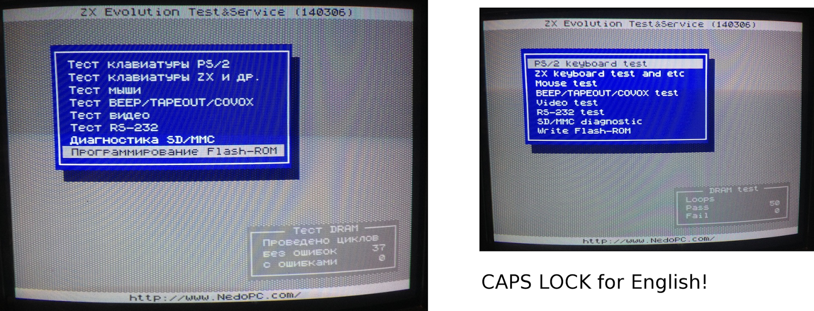
-Go to the last item on the menu and select it. (That says something about a Flash-ROM)


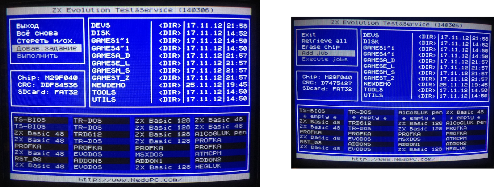
-Here, go to the second last item on the menu and select it.


-Find the zxevo.rom file and select it. 


-All the ROM slots will be yellow. Select.


-Go to the last item on the menu and select it.


-Press Y and wait...


-Everything OK. You can exit this menu from the top item.


-Now it's time to completely turn off the Evo. 

-Copy the first zxevo_fw.bin to the SD card root. This is the actual TS-CONF firmware. Again, overwrite the previous zxevo_fw.bin.

-You should have the WildCommanderWide.$C. Rename it to boot.$c, and copy it on the SD root.

-Flash the firmware: Turn on Evo while holding down the soft reset key. A LED is should start flashing, you can release the key. You should see something like this:


(Remember, pressing Symbol Shift+RESET should always return to this screen.)

-Change the "Reset to:" into BD boot.$c. Press RESET. (There's an alternate RESET that uses Caps Shift+RESET, that's why there is also a  "CS Reset to:")

The Evo boots the boot.$c file. If all is well, you should be in the Wild Commander screen. If there is no boot file or it is incorrectly named, you will have a black/red "system meditation" screen.


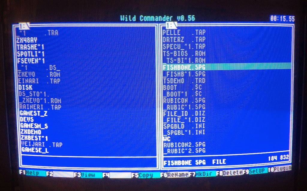
-Select a *.SPG file. I used this one for testing, you should of course copy it on the SD beforehand, or whatever you want to load. (It seems here you cannot load TRD images. Edit: Except if you install the required plug-ins. Check that link...)


That's it!


Wednesday 16 July 2014

Loading JR200 files from Arduino


As a follow-up to Panasonic JR200 tape wave generation some years back, I now had an opportunity to use my specifications for a quick project. Here I have an Arduino UNO work as a "tape" storage for the Panasonic JR200. As the Panasonic JR200 really likes square waves for input, the Arduino digital pins are ideal for the job.

The Arduino produces the waveform over and over from a series of bytes. Using the MLOAD command from the Panasonic end, the computer will load the data next time it loops around. (Resetting the Arduino obviously restarts the "tape")

I spent some time figuring out how to power the Arduino from the Panasonic External Bus, which would be convenient. The first bottom left pin is the Ground. Checking with the multimeter, then, going right, there are five pins between the Ground pin and what appears to be a 5V pin.

Again, I have to say I like the JR200 more and more for the quality of the hardware. I cannot guarantee the below schematic is good for the health of your Panasonic/Arduino/self, but here goes anyway:

Not to scale. The JR200 connectors are as seen at the back of the computer.
I used this setup to load some converted ZX Spectrum loading screens. I noticed the loading can be made somewhat faster, as there's some tolerance in the tape input. At first I used 200 and 400 microsecond square wave lengths to simulate the original speed, but I soon found out that I can use 160 and 320 instead.

So, it might take 26 seconds to practically load a loading screen (4K in two files), that would normally take slightly over 30 seconds. Well, it's a small improvement anyway. At 150ms/300ms, the Panasonic stopped recognizing the signal.


If only I could get rid of the trouble of writing the MLOAD keyword. However, I can at least load BASIC keywords directly into the character display, for example A=USR($1000). So, booting JR200 and using MLOAD would result in a more complex command set, waiting "under the cursor". Machine code can be run from the character display, so a tight package could combine both the necessary keywords to run the code and the code itself.

In glorious flicker-o-vision:


Further ideas:

-Take some signal from the Panasonic to Arduino for triggering the loading. Perhaps the "remote" relay. As the Panasonic gives an audible click when using the MLOAD, there's got to be a relay somewhere.

-The Arduino could just load a short code for high-speed receiving from the joystick port(s).

-Saving files to Arduino. It should be simple enough, but I just can't see the point.


The Arduino sketch:

Copy/Paste to the Arduino editor and upload. Use MLOAD from Panasonic. The example loads just 8 bytes to the character memory. This gives a quick visible effect. For sending your own data, change the contents of the g_data array list. The g_length and g_address are used for setting the start address and the length of the data. The g_offset sets the starting point from which the data is sent, within the g_data array. This only matters if you want to send multiple files.


#include <avr/pgmspace.h>

#define OUTPIN 9
#define MSHORT 200 //160
#define MLONG 400 //320
#define MLONGEST 800 //640

// Panaduino
// Uses Arduino pins to send a tape signal to Panasonic JR-200
// 15.7.2014 Dr. TerrorZ

unsigned int g_level,g_chek,g_blok,g_length,g_address,g_offset;

// The data.
// PROGMEM is necessary for anything longer.
// The actual g_length, g_address and g_offset are set in loop()
// 

prog_uchar g_data[] PROGMEM={1,2,4,8,16,32,64,128};

void switchlevel()
{
  if(g_level==LOW){g_level=HIGH;return;}
  g_level=LOW;
}

void send0_600()
{
  digitalWrite(OUTPIN,LOW);
  delayMicroseconds(MSHORT);
  digitalWrite(OUTPIN,HIGH);
  delayMicroseconds(MSHORT); 
  digitalWrite(OUTPIN,LOW);
  delayMicroseconds(MSHORT);
  digitalWrite(OUTPIN,HIGH);
  delayMicroseconds(MSHORT); 
  digitalWrite(OUTPIN,LOW);
  delayMicroseconds(MSHORT);
  digitalWrite(OUTPIN,HIGH);
  delayMicroseconds(MSHORT);
  digitalWrite(OUTPIN,LOW);
  delayMicroseconds(MSHORT);
  digitalWrite(OUTPIN,HIGH);
  delayMicroseconds(MSHORT);
  g_level=HIGH;
}

void send1_600()
{
  digitalWrite(OUTPIN,LOW);
  delayMicroseconds(MLONG);
  digitalWrite(OUTPIN,HIGH);
  delayMicroseconds(MLONG);
  digitalWrite(OUTPIN,LOW);
  delayMicroseconds(MLONG);
  digitalWrite(OUTPIN,HIGH);
  delayMicroseconds(MLONG);
  g_level=HIGH;  
}

void send0()
{
  digitalWrite(OUTPIN,g_level);
  delayMicroseconds(MSHORT);
  switchlevel();
  digitalWrite(OUTPIN,g_level);
  delayMicroseconds(MSHORT);
  switchlevel();
}

void send1()
{
  digitalWrite(OUTPIN,g_level);
  delayMicroseconds(MLONG);
  switchlevel();  
}

void sendlong1()
{
  digitalWrite(OUTPIN,g_level);
  delayMicroseconds(MLONGEST);
  switchlevel();  
}


void filler600(int a)
{
  int i;
  for(i=1;i<=a;i++){
    send1_600();
  }
}

void filler(int a)
{
  int i;
  for(i=1;i<=a;i++){
    send1();
  }
}

void sendbyte(int a)
{
  int b,c;
  send1();
  send1();
  send1();
  send0();
  b=1;c=a&b;
  if(c!=0){send1();}else{send0();}
  b=2;c=a&b;
  if(c!=0){send1();}else{send0();}
  b=4;c=a&b;
  if(c!=0){send1();}else{send0();}
  b=8;c=a&b;
  if(c!=0){send1();}else{send0();}
  b=16;c=a&b;
  if(c!=0){send1();}else{send0();}
  b=32;c=a&b;
  if(c!=0){send1();}else{send0();}
  b=64;c=a&b;
  if(c!=0){send1();}else{send0();}
  b=128;c=a&b;
  if(c!=0){send1();}else{send0();}  
  g_chek=g_chek+a;
  if(g_chek>255){g_chek=g_chek-256;}
}

void sendbyte600(int a)
{
  int b,c;
  send1_600();
  send1_600();
  send1_600();
  send0_600();
  b=1;c=a&b;
  if(c!=0){send1_600();}else{send0_600();}
  b=2;c=a&b;
  if(c!=0){send1_600();}else{send0_600();}
  b=4;c=a&b;
  if(c!=0){send1_600();}else{send0_600();}
  b=8;c=a&b;
  if(c!=0){send1_600();}else{send0_600();}
  b=16;c=a&b;
  if(c!=0){send1_600();}else{send0_600();}
  b=32;c=a&b;
  if(c!=0){send1_600();}else{send0_600();}
  b=64;c=a&b;
  if(c!=0){send1_600();}else{send0_600();}
  b=128;c=a&b;
  if(c!=0){send1_600();}else{send0_600();}  
  g_chek=g_chek+a;
  if(g_chek>255){g_chek=g_chek-256;}
}


void header(int id)
{  

  //in 600 baud format

  g_chek=0;
  sendbyte600(2);
  sendbyte600(42);
  sendbyte600(0);//block#0
  sendbyte600(26);//fixed length of data for block #0
  sendbyte600(255);
  sendbyte600(255);
  sendbyte600('P');//filename 16
  sendbyte600('D');
  sendbyte600(48+id);
  sendbyte600(0);
  sendbyte600(0);
  sendbyte600(0);
  sendbyte600(0);
  sendbyte600(0);
  sendbyte600(0);
  sendbyte600(0);
  sendbyte600(0);
  sendbyte600(0);
  sendbyte600(0);
  sendbyte600(0);
  sendbyte600(0);
  sendbyte600(0);
  sendbyte600(1);//binary1,basic 0
  sendbyte600(0);//baud rate for the rest. 0=2400, 1=600
  sendbyte600(255);
  sendbyte600(255);
  sendbyte600(255);
  sendbyte600(255);
  sendbyte600(255);
  sendbyte600(255);
  sendbyte600(255);
  sendbyte600(255);  
  sendbyte600(g_chek);//checksum
}

void datablock(int len)
{
  unsigned int i,adhi,adlo,lbytes;
  unsigned int bb;
  unsigned char cc;
  lbytes=len;
  if(len==0){lbytes=256;}
  g_chek=0;//reset checksum
  adhi=g_address/256;
  adlo=g_address-(adhi*256);
  sendbyte(2);
  sendbyte(42);
  sendbyte(g_blok);//block nro
  sendbyte(len);//length 0=256
  sendbyte(adhi);//hi addy
  sendbyte(adlo);//lo addy
  for(i=0;i<=lbytes-1;i++){
    bb=0;
    cc=pgm_read_byte_near(g_data+(g_blok-1)*256+i+g_offset);;
    bb=int(cc);
    sendbyte(bb);
  }
  g_address=g_address+lbytes;
  sendbyte(g_chek); 
}

void lead_out()
{
  int adhi,adlo;
  adhi=g_address/256;
  adlo=g_address-(adhi*256);
  sendbyte(2);
  sendbyte(42);
  sendbyte(255);
  sendbyte(255);
  sendbyte(adhi);//hi addy
  sendbyte(adlo);//lo addy
}

void send_tape(int tapeno)
{
  int i,dblocks;
  int lef;
  
  dblocks=g_length/256;
  
  g_level=LOW;
  g_chek=0;  
  g_blok=1;
  
  //600 baud portion
  filler600(850);
  header(tapeno);
  filler600(51);
  
  //2400 baud portion
  for(i=0;i<=dblocks;i++){
   if(i==dblocks){
     lef=g_length-dblocks*256;
       if(lef==0){datablock(1);}
       if(lef>0){datablock(g_length-dblocks*256);}
     }
   if(i<dblocks){datablock(0);filler(196);}
   g_blok++;
  }
  
  sendlong1();
  filler(188);
  lead_out();
  sendbyte(255);
  filler(150); 
}

void setup()
{
  pinMode(OUTPIN,OUTPUT);
  digitalWrite(9,LOW);
  pinMode(13,OUTPUT);
  digitalWrite(13,LOW);
}

void loop()
{ 
  g_length=8;
  g_address=0xd000;
  g_offset=0x0000;
  send_tape(1);
  
  pinMode(OUTPIN,OUTPUT);
  digitalWrite(9,LOW);
  delay(100);
  
  //for multiple MLOADs, use separate tape loads.
  //delay(1500);
  //g_length=0x0800;
  //g_address=0xc100;
  //g_offset=0x0800;
  //send_tape(2);
}