Looking at a promising recent z80 cross-assembler and Arkos Tracker 2. Both work on Linux and there are now easy-to-use music player routines for ZX Spectrum included.
The assembler compiles the player routines without any modifications so it made sense to me to lump my notes together here.
It couldn't get much easier for the Linux user I think!
Rasm
Rasm is the z80 cross-compiler. (The R stands for Roudoudou I suppose). Download the Rasm archive, extract it to a folder.
Look for the compilation instructions inside the c file, something like
cc rasm_v0108.c -O2 -lm -lrt -march=native -o rasm
(Edit 30.8.2022: These days makeseems to work as it should. If compilation stops at stdio.h or string.h, may need sudo apt install build-essential before attempting.)
After copying the output rasm to say /usr/local/bin, you can then use rasm inputfile.asm to produce an instant binary from out of the source.
The inputfile.asm contents might be something trivial like this:
org $8000 ld hl,#4000 loop: inc a inc l ld (hl),a jr loop
This should fill the top third of the screen with garbage.
The black screen comes from the bin2tap BASIC header
When the binary rasmoutput.bin (the default name) has been created, it still needs to be converted to a TAP file that a Spectrum could load.
Using the bin2tap(need to compile that too) you can create a runnable tape with a BASIC header. By default it works with the $8000 (32768) address so no need to worry about that either. Again, it ought to be copied to /usr/local/bin (for example).
Then, working with the default output binary name:
bin2tap -b -o mycode.tap rasmoutput.bin
After this, Fuse will happily load the produced mycode.tap and use the BASIC loader to load the binary and execute it at 32768 ($8000).
Rasm is a clever modern macro-assembler with all the repeat functions you'd expect nowadays. With a good editor like sublime-text (with added z80 highlighting) it's a breeze.
For example, the following will generate a table of 192 start addresses for each vertical pixel row, often needed in ZX Spectrum graphics routines:
screenbase=$4000 ytable: repeat 3,yblock repeat 8,ychar repeat 8,ypixel dw screenbase+(ychar-1)*32+(ypixel-1)*256+(yblock-1)*2048 rend rend rend
Using variables, evaluations and local labels inside repeat blocks even quite complex repetitive code can be generated.
Arkos Tracker 2
More information about Arkos Tracker from here. Extract the archive and simply run.
I'm not going too deeply into song creation here, suffice to say this is the easiest cross platform 8-bit tracker I've seen, with an audible default instrument and preset instrument categories for bass, snare etc.
After the pattern has been filled with bleeps and bloops, you can export the creation from the menu option file/export as generic (AKG), choosing source as the export mode.
Pick the PlayerAkg_SPECTRUM.asm from the players/playerAKG/sources folder, and copypaste the contents to the end of your source. (Of course it would be a better practice to include the player routine and the song.)
For example, this is a minimal main loop that will HALT the Spectrum until the next frame, and call the 'play frame' portion of the player routines.
org $8000 ld hl,Songname_Start xor a call PLY_AKG_Init loop: halt call PLY_AKG_Play jp loop ; paste the PlayerAkg_SPECTRUM.asm contents here ; paste the Songname_AKG.asm contents here
The exported song source can be copypasted after the player source. The Songname obviously refers to the filename it was exported with.
The start address is not needed so the org line may need to be removed from the song source. As can be seen the player nicely accepts a flexible start address - no need to copy the song data to some specific address either.
My example is simple, it's not especially useful to simply HALT and call the player routine, it might be better to use an interrupt to play the song.
But this is it for now, I'm super-impressed how easy this was to set up and get running.
One day, I thought it might be possible to re-create my Fort Django on the ZX Spectrum. I abandoned this exact goal as there's not that much material that can be re-used and some of my findings discouraged me from this route.
Instead the code became an exercise in game sprite graphics. I wanted to have three huge-ish characters on screen with a smooth framerate, with a game that would again float somewhere near the Saboteur!, Bruce Lee and Dan Dare territory.
I decided on XORed sprites, so I don't have to do masks. XORing graphics means that the underlying pixels are inverted with the sprite pattern. It's a nice method in that with XOR the sprite drawing and erasing routines are exactly the same, because re-drawing on the same position leaves the screen as it was before drawing.
Granted, it can look a mess whenever the sprites overlap. Many complained about colour clash in ZX Spectrum games, but I guess XOR was partly to blame, too. Atic Atac is maybe the best game that uses the XOR approach, and it's very fast.
Early days. Using sprites adapted from Fort Django
I needed to plan the graphics and the game around the XORing artefacts, so it would not get too bothersome. This was the reason to move away from the Fort Django concept, as the ladders and furniture might create too many disturbances around the moving, overlapping graphics.
Another weird technique is to draw the sprites when entering the frame and erasing them on the way out. With a Commodore 64 you could simply check for the suitable scanline, but with a ZX Spectrum this is not possible. I'll simply have to ensure that each frame still does the same things even if there are no enemies on screen. This also means the game is fixed for the 3.5MHz timings. Such an approach is not very elegant nor portable, but it's justified to get a silky-smooth game in a closed environment that the 8-bit computer is.
The sprites, actually
Although XORing is a fast technique, I still had to revise my approach a bit. My initial target of 40x64 sprites with smooth framerate were clearly out, so I went for 40x48 instead, which is the size of the Saboteur human characters.
I can't even have true 40x48 sprites, but by doubling the vertical pixel size it is possible. Not only are the pixels doubled, but the underlying vertical screen resolution needs to be divided by two to make the XOR draw/redraw logic work. So I'm working with 256x96 screen with 1x2 proportioned pixels.
Drawing one "line" of the sprite data as 1x2 pixels.
This has the benefit that as I fetch the sprite graphics, I can assume the two subsequent screen line contents are the same, so the routine does not have to read them separately.
The sprite graphics are drawn from left to right, zig-zagging the two lines. The stack is pointed to a table that has the vertical screen addresses sorted out for every other pixel row coordinate, and these addresses are pop'ed for each sprite line. The horizontal component of the address needs to be added, too.
1x2 pixelled sprite data pictured in GIMP, with one data line highlighted.
The sprite Y-coordinates are also constrained to multiples of 2. This has the benefit that there is never a troublesome screen address boundary between the zig-zagged vertical pixel rows. Within the line, the zig-zagged pixel row can be changed with just incrementing or decrementing the address high register.
Other good things came out of the 1x2 pixels: Instead of needing 256 bytes for each sprite frame, I could fit a graphic frame inside 128 byte boundaries. The 40x64 sprites would not have fit in a 256-byte boundary anyway.
The pixel ratio is not that limiting, as the sprites can be drawn deal with it rather than stubbornly make something that does not fit. My current sprites are hardly the pinnacle of ZX graphics, but it looks promising. And of course the screen portions where the sprites are not drawn, can be in 1x1 pixel format.
Toying around with some gfx pretty much ripped from Dan Dare.
With this tweaking of the resolution I could draw apparent 40x48 pre-shifted pixel areas three times, after which the scanline is at the 16th line of the Display File. This would mean that a moving sprite at the top of the screen could become distorted.
I could use a portion of the screen for a dashboard, as in the image above, and these 16 lines might not matter. I am making a game after all, and not a generic sprite routine.
But then the silly me realized that if the sprites are drawn in a certain order, the scanline intrusion can be made nearly meaningless: If the first sprite to be drawn is at the top of the screen, the second at the middle of the screen and the third in the bottom of the screen, all happens smoothly by "racing the beam". I only have to take care that not all sprites move near the top or bottom at the same time.
The diagram below shows what happens during one frame. These are not based on actual values, the picture is exaggerated for clarity. In this example only the second sprite is truly both a: drawn before the scanline enters the pixel drawing area, and b: erased after the scanline leaves the pixel drawing area.
This brings certain limitations to what can be performed with the sprites in the game. For example, only the player character has full freedom to move all around the screen, whereas the other sprites would stay within invisible "cages". Yet these cages are so lax that by switching sprite positions these cages do not matter much.
Technically, it would even be possible to draw more sprites than the three, if the sprite drawing order is well managed. This is somewhat equivalent of multiplexing sprites on computers that have real sprites and good scanline routines. But I felt this might become a bit too complex programming exercise or limit the "cages" a bit too much.
So, there are now three "big sprites" and the player sprite is always the second sprite to be drawn. The game, whatever it might be like, has to be designed around the small limitation that the enemies can't go everywhere.
Animation frames were another source of trouble. I wanted to save frames by "baking in" the leg motion inside the shifted frames. But this produced too fast animation. So instead of four shifted frames there would be eight sprite frames for simply making the guy walk on screen. The eight frames make a total of 1K graphics laid out in 128-byte address boundaries.
What else? I didn't make a clipping routine, even if it's not too slow to check the coordinates and divert to another sprite drawing routine. I wanted to negotiate some programming time out of this project.
Dude, where's my game?
So, after making the to-hell-with-portability sprite engine, I could concentrate on the game. All I've made since the sprite routines is a tile-drawing/collision routine, a bit more joystick stuff and experimenting with ways to draw unobtrusive objects. It looks nice, but currently a bit limited for a proper game. I'll get back to this in some form, but it doesn't seem to happen anytime soon.
I got hold of some Quickdisk disks, Roland brand. So far I've had no luck with software. I've played around with formatting the disks and using the built-in monitor for storing binary files.
The Sharp MZ-800 monitor inside the ROM has usually these few commands on offer:
M-View/Edit memory (Example: MC000)
D-View memory (Example: DC000)
B-Turn beep on/off
L-Load from tape
S-Save to tape
Shift+BREAK usually aborts any operation.
With the Quickdisk drive connected, the computer switches to a different ROM. The monitor then hosts these additional commands:
Each of the command is typed as a two-letter entry, without parameters. The monitor then asks the relevant information, such as filename, start, end and execution addresses.
It seems that DELETE/KILL is out of the question, so, at least without an operating
system (Disk BASIC) the only way to make space is to reformat the disk.
The files need to have an execute address, and it is always used when the file loads. The auto-execution may be circumvented by using 00AD as the start address. Another route might be to choose a RAM address to which all the data files point to, and ensuring there's something meaningful at that address.
The Quickdisk loads 16 kilobytes in 4 seconds. On startup, the MZ800 boots to a disk file as long as there is a file on the disk, regardless of the filename. To bypass this I had to hold the disk drive cover open when resetting. The boot is rapid, which might be because the QD ensures the idle drive head position always points at the beginning of the first file. (=the boot file)
Using the D command for displaying memory contents. QD shows three files on the disk. The machine code at C000 messes with the character display.
I've used the following machine code for testing purposes. Located at $C000, it continuously increments the contents of the first 255 bytes of the character display, beginning at $D000. Quick to type, yet gives a visible enough effect. Use MC000 to start typing in the hex at the left. Shift+Break exits the entry mode, and JC000 will run it.
It is a truth universally acknowledged, that as the ZX Spectrum does not have hardware sprites, the programmer is left to concoct her own bitmap graphics routines. It's
something every aspiring Spectrum coder should try to do! Recently me and Marq have been exploring fast and smooth sprite graphics on the 48k Speccy. It's a much discussed topic, yet remains fascinating. Moving graphics can be done in so many ways, and it is not always obvious what to aim for. Games use various tricks to ease the load, and the tricks in turn depend much on what the game is about.
It's still wise to try to build a generally useful sprite engine, before optimizing for different contexts. So far we have managed eight 16x16 masked, freely positioned, flicker-free, smoothly moving sprites, as shown in the above video. (Check also this Youtube video)
This first part opens up the basics of the topic. If I get to write an improved version, there will be a Part II.
A 16 x 16 sprite is a common starting point. Any problems related to it can be applied to larger sprites. The above image shows a 32-byte definition of such a sprite. From left to right, top to bottom, the bits would translate to following decimal bytes:
This corresponds to the way the Spectrum stores pixels, one bit per pixel, a byte for eight pixels. The memory-mapped screen is found from the address 16384 onwards. A POKE 16384,255 in BASIC will quickly show this.
Screen BASICs
The ZX Spectrum display is notoriously a bit disordered, so one of the first issues is to resolve the drawing order. At first glance, it would seem to be enough to increment the drawing address with one byte for each column and 256 bytes for each row. Then, a routine like the one below would render our sprite on screen:
5 REM DOES NOT WORK
10 LET ADD=17184
20 FOR B=0 TO 15
30 READ L
40 READ R
50 POKE ADD,L
60 POKE ADD+1,R
70 LET ADD=ADD+256
80 NEXT B
100 DATA 7,224,24,24,32,4,78,2
110 DATA 95,2,159,1,142,1,128,1
120 DATA 128,1,128,1,128,25,64,58
100 DATA 64,50,32,4,24,24,7,224
If only:
Uh oh.
But we're on right track somehow. At least something is happening on screen. As it stands, the address logic changes after every eighth pixel row, as shown in the diagram below. The picture shows in detail the structure of the top left corner of the Spectrum screen, where I tried to draw my sprite. Inside the character row, each pixel row is nicely 256 bytes apart, but the first addresses of each character row are 32 bytes apart.
Furthermore, the screen is divided into three 64-pixel high "slices", each having a start address 2048 bytes apart. Zooming out, the leftmost screen addresses for each character row (every eighth pixel row) are laid out as follows:
This ordering is quite good for drawing 8x8 characters aligned to the character rows. One might even call the Spectrum screen layout a pseudo-character display. But a generic sprite routine has to negotiate the 8-line "boundaries" as well as the two "slice" boundaries.
The BASIC program below identifies the slice block and character rows for a given vertical pixel coordinate, and draws the "sprite" accordingly.
10 FOR S=0 TO 15
20 LET Y=11+S
30 LET BLOCK=INT (Y/64)
40 LET CROW=INT (Y/8)
50 LET YR=Y-(CROW*8)
60 LET CROW=CROW-(BLOCK*8)
70 LET ADD=16384+BLOCK*2048+CROW*32+YR*256
80 READ L: READ R
90 POKE ADD,L: POKE ADD+1,R
100 NEXT S
110 DATA 7,224,24,24,32,4,78,2
120 DATA 95,2,159,1,142,1,128,1
130 DATA 128,1,128,1,128,25,64,58
140 DATA 64,50,32,4,24,24,7,224
OK, indeed
The object described here hardly deserves the name "sprite". BASIC is simply too slow, and there's lot more to do than just laying the bits on screen. Proper sprite routines can only really be done in machine code.
Even then, it's possible to improve the above listing, by calculating the addresses beforehand into a table. It would be a bit silly to calculate the address for each sprite row.
10 REM PREPARE A TABLE
20 DIM A(176)
30 FOR Y=0 TO 175
40 LET BLOCK=INT (Y/64)
50 LET CROW=INT (Y/8)
60 LET YR=Y-(CROW*8)
70 LET CROW=CROW-(BLOCK*8)
80 LET ADD=16384+BLOCK*2048+CROW*32+YR*256
90 LET A(Y+1)=ADD
100 NEXT Y
110 REM DRAW THE SPRITE
120 RESTORE 180
130 FOR I=0 TO 15
140 READ L:READ R
150 POKE A(11+N),L: POKE A(11+N)+1,R
160 NEXT I
170 DATA 7,224,24,24,32,4,78,2
180 DATA 95,2,159,1,142,1,128,1
190 DATA 128,1,128,1,128,25,64,58
200 DATA 64,50,32,4,24,24,7,224
At least in this respect, writing sprite routines in assembler is not that different. It's about finding ways to offload the burden from the drawing parts. This is why many fast routines use a buffered drawing of some sort.
Sprite shifting
The BASIC listings simplified many things. Much has been said about the vertical coordinates. How about the horizontal? Fiddling with the BASIC listings above would show that adding one to the sprite position address moves the sprite one character column to the right. This at least is straightforward, but it is not smooth. There are ways to recalculate the sprite graphics on the fly, but pre-shifted sprites are easier and faster.
A 16x16 sprite GFX and its' mask, with room for shifting.
Shifted 16x16 sprites are in reality 24x16 sprites, and each graphic needs 8 shifted variants. This way they can be aligned horizontally with the character columns. The downside is that it takes more memory.
All the sprite variants also need a mask, which is an inversion of the area that will be cleared before drawing the proper sprite. This way the sprites can be drawn over a background without showing any of the pixel background through the sprite, or producing other ill effects. Many games get away without using masks or backgrounds, and can even look better for it (think Dan Dare), but such an approach is hardly generic.
The machine code routines discussed below use shifted sprites.
Sprites in z80 machine code
Smooth sprite movement has to be tied to the screen update cycle, which is refreshed 50/60 times a second. In machine code, the HALT instruction tells the processor to wait until the refreshing beam has returned to the top of the screen.
After this, the beam travels right, returns to the left side of the screen and travels down, refreshing the screen during the process. To avoid flickering and glitches, changes to the screen should be done before the beam hits the drawing area.
So, a conventional sprite-drawing program might follow this order:
The z80 running at 3.5mhz can do quite a bit before the beam is arrives at the pixel area. (Or "the display file" as it is called in the official Spectrum manuals.)
Of course, even when the beam is in the pixel area, things can be drawn below the current beam position, and the results will still be smooth. Many scene demo effects take advantage of "racing the beam" in this way. Even a sprite routine may benefit from such a scheme, but for a generic routine the drawing is safest to do before the beam arrives at the pixel area.
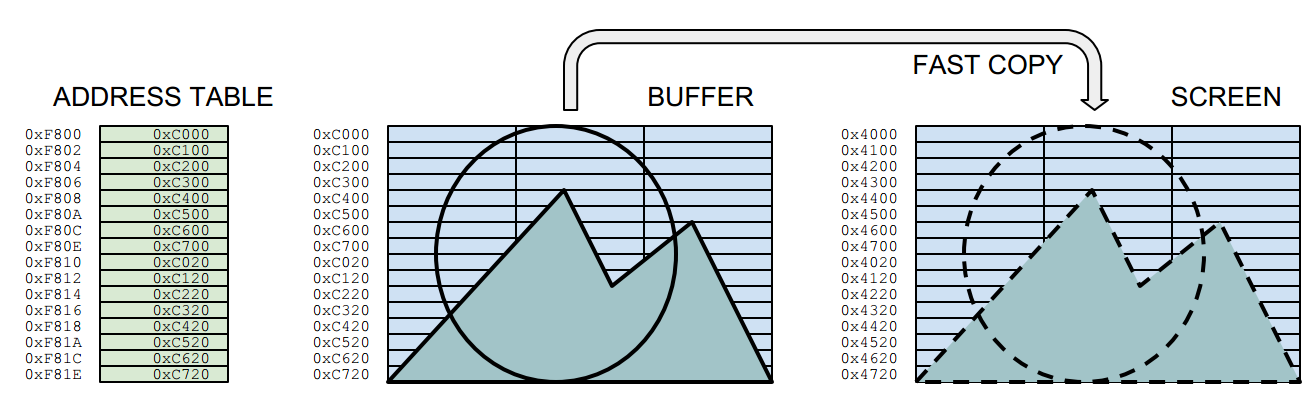
The sprite program shown in the video follows the order below. The border colours are not just for fun, but for showing what actions are being taken at that scanline position. The routine draws the sprites into a hidden buffer screen, and uses a fast copy routine to do bring them on the visible screen. An address table holds the position information for the fast copy routine.
BEFORE THE LOOP:
Copy the entire background image to the entire buffer
Draw sprites to buffer and create a new address table for them
LOOP PHASES:
Wait Vertical Blank (=HALT instruction)
RED: Copy bytes to screen from buffer, using the sprite address table
BLUE: Copy background to sprite positions at the buffer, using the sprite address table
YELLOW:Change sprite coordinates
BLUE: Store the address table
YELLOW:Draw sprites to buffer and create a new address table for them
BLACK: Wait until the beam is outside the pixel area (estimated)
RED: Copy background to sprite positions on the screen, using the stored address table
The sprites are drawn when the beam is on its "way in" to the pixel area, and wiped out on the way out. It is a bit unelegant to have to wait at the end, as the waiting time depends on the computer speed. So, this solution is fixed for the original 48k Spectrum timing.
Note that here the sprites are drawn well before the beam arrives at the pixel area. The fast copy routine could even move 12 sprites to the screen. Yet drawing more than 8 sprites altogether (buffer, clearing) is not yet possible. It's easy to see though, that there are ways to reduce the load, especially the needless duplicating of the address table.
Buffered drawing
In this sprite routine, there are three "screens": The real display screen, a source background image and the drawing buffer. In addition, the sprite graphics need to be stored somewhere.
The diagram below shows the Phase 6 in the above list. (The second "yellow" portion.) Here we draw the sprite to the invisible buffer screen and store its screen position as an address into the sprite address table for later copying.
The actions required for drawing a single byte are highlighted. The diagram only shows the part relevant for the sprite, which in this case is drawn to the top left corner of the buffer, waiting to be moved on the same relative screen position. The mask and graphics are interleaved for purposes which is explained later.
Phase 6: The diagram illustrates how the sprite is drawn into the buffer screen.
Each time the sprites are drawn to the buffer, an address table is also renewed. The address table is at the heart of the fast drawing routine (phase 2). One sprite has 16 rows, so drawing a sprite to the buffer also writes 16 addresses to the table. The address table points to the locations in the drawing buffer, from which the sprites are copied after the HALT:
Phase 2. Fast copy from the buffer to the screen
This means a lot of the calculations needed for computing the outcome (such as the row boundary calculations and combining the mask/background) are done in hiding, whereas the fast copy is only concerned with moving bytes directly between the buffers and screen areas.
In z80 assembler, the fast copy might look something like this:
buffercopy:
ld sp,#addresstable
pop hl ; row 1
ld d,h
ld e,l
res 7,d
ldi
ldi
ldi
pop hl ; row 2
ld d,h
ld e,l
res 7,d
ldi
ldi
ldi
pop hl ; row 3
ld d,h
ld e,l
res 7,d
ldi
ldi
ldi
...
...
...
[16 rows for each sprite]
addresstable:
; Just an example, a sprite in the top left corner
The stack pointer is placed at the beginning of the table, and the addresses are loaded in the HL register using POP HL, which also increments the stack pointer by two. The LDI performs the equivalent of LD (DE),(HL), moving the contents from address at HL to the address at DL, incrementing both DE and HL in the process. For 24-pixel wide sprites, three LDIs are required for one row.
The table could have from-to address pairs, but writing both addresses during buffer drawing proved to be a bit cumbersome. So the "destination" address DE is constructed out of the "from" address HL by altering the high byte. This is a tiny bit slower than POP:ing both from the table, but it also keeps the table shorter for copying purposes. (phase 5)
This address shifting also means the buffer locations cannot be freely chosen. 0XC000 (49152) and the screen address 0X4000 (16384) are in a good relation to each other, as only one bit needs to be changed between them. There are three versions of the above routine, all different depending whether it is about BUFFER->SCREEN, BACKGROUND->BUFFER or BACKGROUND->SCREEN copying.
The lines
Let's get back to where we started: The ZX Spectrum screen order. Despite the fast copying routines, the sprites need to be drawn into the buffer, and at least somewhere during the process, the line order needs to be negotiated. It's no good if the buffer drawing routines, even if hidden, are too slow.
The overall assembler source is a bit too daunting to publish here, as it is largely a Processing-generated bundle of tables and repetitive code, held together with some C. So I'll stick to explaining the overall idea and some of the more interesting points.
Obviously there has to be a table that contains the drawing address for each vertical pixel row. But accessing this table 16 times each time a sprite is drawn would be less than optimal. This can be avoided. But if one wants to avoid conditional jumps (and one wants to avoid them) there has to be a number of variants of the routine, depending on which pixel row the sprite is drawn to.
With eight sprites, any commands added to the pixel drawing order gets repeated not only 8 times, but 128 times or more! So there's a great incentive to remove slow code from the heart of the buffer drawing.
It would be neat to just have a full sprite drawing routine for each vertical pixel row. This would produce 175x16 copies of the sprite row drawing code, which takes far too much memory. The amount can be reduced: there are only 23 ways how a 16-pixel high sprite drawing might unfold. This would produce "only" 23x16 times the row drawing code. It doesn't sound much but still it's more than 20 kilobytes, a bit too much.
What we did was a bit nasty: self modifying code. One pixel row drawing code is repeated only 39 times. Each variant has it's own labeled entry point. When the sprite drawing is invoked, the program jumps into the relevant entry point, depending on the sprite vertical coordinate. (Yet another table) The diagram below describes the whole code portion and an example case:
The example sprite is to be drawn at Y coordinate 20. A vertical address table tells that this row uses the variant 4. The NOP (0x00) instruction at the address of EXIT4: label is overwritten with a RET (0xC9) instruction. HL is loaded with the label ENTRY4: address. JMP (HL) takes the program counter there.
The routine then draws four rows, skips the character boundary, draws another eight rows, skips another character boundary, draws four more rows and exits the drawing routine. The RET is overwritten with a NOP.
There have to be rewritten exit points, because only 16 rows are needed, and we want to avoid conditional jumps and wasting registers on counters. So, drawing sprite variant 0 means jumping to the entry label 0, while writing a RET to the EXIT0:. Jumping to entry 4 means writing a RET to the exit point 4 and so on.
The code below describes what happens within the "draw row" portion in the above diagram.
; stack is pointed to the beginning of sprite graphics
; (mask and gfx interleaved)
; de holds the drawing address
; jp(hl) brings the program counter here
; bc holds the beginning of the address table
ENTRY0:
; de is written to the address table
ld a,e
ld (bc),a
inc bc
ld a,d
ld (bc),a
inc bc
; draw one sprite row to the buffer (3 bytes wide)
; stack handily gives both the mask and the graphic byte
ld a,(de) ;get buffer byte
pop hl ;get mask and gfx
and a,l
or a,h
ld (de),a ;draw to buffer
inc e ;right
ld a,(de) ;get buffer byte
pop hl ;get mask and gfx
and a,l
or a,h
ld (de),a ;draw to buffer
inc e ;right
ld a,(de) ;get buffer byte
pop hl ;get mask and gfx
and a,l
or a,h
ld (de),a ;draw to buffer
EXIT0:
nop ; may be overwritten with ret
After the pixel row, the destination address is adjusted for the next pixel row.
; normal
dec e ;left
dec e ;left
inc d ;down
If the next address crosses the character row, this will be used instead:
; pass the character row boundary
ld a,e
add a,#30
ld e,a
ld a,d
sub a,#7
ld d,a
Or, finally, if the next pixel row is beyond the slice block boundary, this is needed:
; pass the slice block boundary
inc d
ld a,e
add a,#30
ld e,a
That's it for the time being. We think this routine can still be significantly improved. Perhaps the nasty self-writing can be avoided. Perhaps it might be possible to get rid of the un-elegant wipe at the end of the screen. There are some wild ideas brewing, but better not boast about them before they are real...