Showing posts with label zx evolution. Show all posts

Thursday, 13 June 2019

ZX Evolution joystick port


A tiny upgrade for my ZX Evolution computer, housed inside an Antec mini-ITX case.

As an aside, when I opened the case from the wrong side I noticed there's room for a drive below the motherboard. This has nothing to do with the joystick but I thought I'd add this memo to self here too.


Anyway, the joystick

Sinclair ZX Spectrum had no definite joystick standard, even though Sinclair had provided their own with the Interface I/II. Many games offered the selection between Keyboard, Cursor(joystick), Interface II/AGF/Protek, Fuller, Kempston/12L...

I suppose most if not all, accepted an Atari 9-pin standard one-button joystick. How the inputs were read by Spectrum differed. The interfaces were produced by third parties, and some did not interfere with the keyboard input unlike the Sinclair solution.

Not an unlikely choice
Kempston was the most popular and became a de facto standard. As a child I didn't have a clue what the word meant, but now it's easy to check that Kempston is a town in the UK, and Kempston Micro Electronics is the company that produced these interfaces. They also made some joysticks of their own.

Even after other companies produced compatible interfaces the name somehow stuck. I guess British video game companies and Sinclair also preferred not to have the name 'Atari' shown around so it made common sense to call it something else.

The publisher Ultimate could have helped cement the name and the standard, as they supported Kempston in their games and their games were hugely popular of the early lot.


Making the port

ZX Evolution supports the Kempston IN 31 standard with on-board pins, so there's no need to solder anything. I could also connect to the suitable keyboard rows to make a cursor joystick, but I went for Kempston/Atari.

I had a COM-port extension back panel for PC lying around, and after salvaging the actual connector it could be used as the joystick port.

I had previously connected a transparent acrylic panel to the backside of my ZX Evolution case, which houses the likewise DIY connector for RGB.

This kind of plastic is a bit too hard and tends to break when mistreated. At least the two holes on both sides of the connector are smooth.


I then continued to drill holes to cut out the shape for the interface.

I turned the drill along the direction of the cut to get it behave bit like a saw. This is something I should not have done, but I had no other solution at hand and the whole piece of acrylic might have fractured had I used a larger drill.


I finalized the cuts with a small saw and the center piece fell out. The result was smoothed a bit with a file.

It's a bit crude as the connector is attached from behind and doesn't have the covering piece of metal the RGB connector (that DIN a bit further off) has. However it stays in place firmly and that's enough.


At the top, the new 9-pin Joystick port and the RGB connector. Below: SD, RS-232, micro-USB, VGA and audio/tape plugs.

I had a go at Atic Atac using a TAC-2 joystick. This is the first Spectrum game I recall playing with a joystick, and to my surprise I could now complete it easily. Just remember not to eat every 2nd food so you'll have more spares later :)


Sunday, 14 April 2019

ZX Spectrum ULAplus mode, Multipaint etc.

I was asked to do ULAplus extended ZX Spectrum graphics mode support for the Multipaint painting software.

I was initially reluctant. Multipaint supports only the most established and "culturally recognized" modes, and I've not bothered to make C64 FLI/AFLI modes either, and they don't even require new hardware.

But I then saw that some images might actually come out of it, and seeing as I already own hardware that can display the mode (ZX Evolution) my curiosity grew. It's a challenging mode to work with, and Multipaint might help here.

I suppose a fairly huge proportion of currently active ZX Spectrum enthusiasts would be at least aware of the ULAplus mode. Although there are many modded and patched games and converted images that use the palette, the lack of editors and paint programs means Multipaint could even fill a niche here.

I'd usually prefer to release things before discussing them, but here I'll make an exception as there's a bit more to digest than usual.


ULAplus hardware?

In addition to the already mentioned ZX Evolution, I know about a ZX-UNO computer that has it. Then there is the SLAM drop-in ULA replacement which works on 128k or a +2.

A HDMI video board called the TK-Pie appears to promise these modes too.


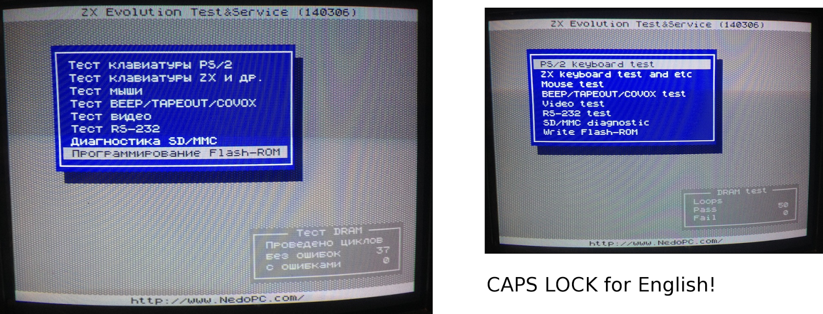
Emulators also support the mode. I couldn't get my Linux Fuse patched to support it, but I have the mode working on ZX-UNO emulation within the ZEsarUX emulator. There I have to switch the mode on in the Display segment of the settings menu.


ULAplus and ZX Evolution

I had to update the firmware of my ZX Evolution to make this mode work. The firmware you get from one of the nedopc pages is not recent enough, so I went to GitHub and downloaded the latest zxevo_fw.bin and zxevo.rom. (Go look for the ROM at pentevo/rom/bin/)

I cannot guarantee this is the best option for your ZX Evolution, but at least I have my ULAplus mode working on a hardware speccy.

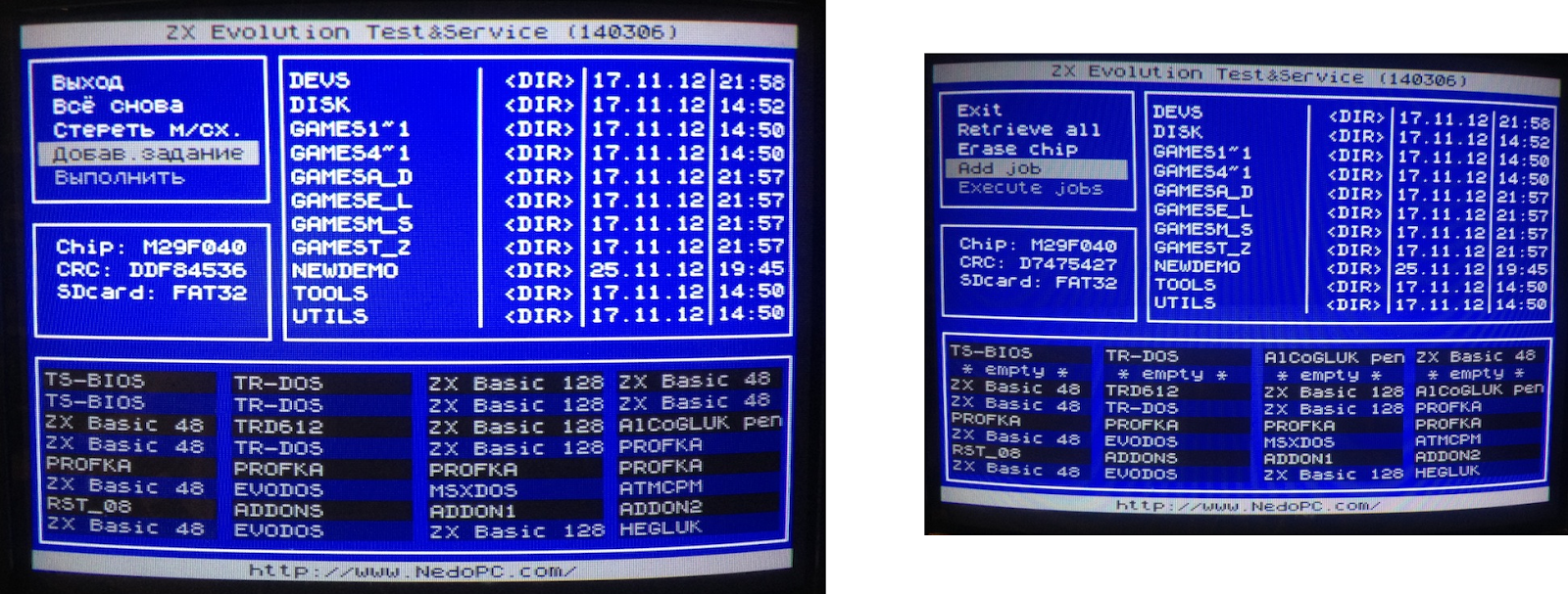
Upgrading the firmware was easy as I have my Evo inside a mini-ITX case. Wired correctly, I can then copy the zxevo_fw.bin to the SD card, and simply hold down the "soft" power button while plugging the cable in. The power LED flashes a bit and the firmware has been upgraded. These days the ZXevo ROM can be updated from within the baseconf service and it is a good practice to have both the ROM and the firmware updated at the same time.

ZX Evolution does not have a full ULAplus mode, it omits the difference between 6th and 7th level of the Red and Green components. So it might be something to consider when making graphics on the ULAplus.


ULAplus mode in Multipaint

Here I focus on how ULAplus works in practice and what it might mean for someone using Multipaint, although it's not yet definite how it will work.

ULAplus is clever in that it does not make the Specrum incompatible, it simply changes what is done with the memory bits that make up the display file. So, I'm only talking about the most standard mode, which has the same old resolution of 256 x 192 and the 32 x 24 attribute resolution with 256 colours to choose from.

The attribute "clash" is not removed, there are still two colours inside an 8x8 area, and much like with the ZX Spectrum there are rules to how these colours can be chosen.

But as there are more colours and they can be combined in more flexible ways, the look of the graphics can be changed quite radically. I'd go as far as to say the ULAplus experience proves the colour clash wasn't such a huge problem with the original ZX Spectrum, the limited colour palette was.

Here's a diagram that may be more confusing than helpful, but let's try it out:

From Multipaint painter's perspective:

-There is an index of 64 colours.
-These 64 colours can be adjusted with RGB sliders from a total of 256 colours. It is a kind of semi-9-bits RGB palette.
-The 64 colours are really four sets of 16 colours. No colours from two different 16-colour sets can be mixed inside the 8 x 8 area.
-Each of the 16-colour sets are further split into two subsets of 8 colours. The colours inside the 8x8 must be from a different subset. ("INK" and "PAPER")

Just as in the normal ZX Spectrum mode, Multipaint does not care which colour is INK or which is PAPER. This is why I have described the mode in a bit idiosyncratic way.

The internal workings can be partly forgotten by the artist, but still ULAplus is more complex than the ZX Spectrum limitations and it would be better if the artist understood these rules.

My starting point for the ULAplus Multipaint engine was to first prevent any pixel drawing operations that cannot be done, and then attempt to fill in the gaps with some helpful intelligence, without going overboard with this "helpfulness".

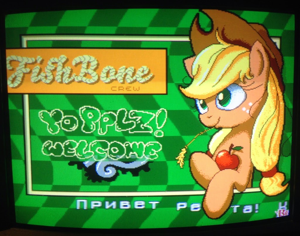
An early test of the TAP export, shown on the screen of a ZX Evolution computer.
The 16-colour set is technically called a Colour Look-Up Table (CLUT) and I will now follow that terminology here.

So, if the pen colour is from another 16-colour set (CLUT) than the colours underneath, then Multipaint likely won't allow you to draw on it.

If there is no diversifying pixel information at all within the 8x8 cell (it is filled with 64 pixels of the same colour) and it is not legal to draw with the current pen colour, it will be "primed" by Multipaint with the chosen colour. The area will also belong from that point onwards to that CLUT.

However, if the pen colour is legal the pixels will be added on that square and from that point on it will have two colours in it.

So, two different halves of a CLUT combine to make the colours on the same 8x8 area. It doesn't matter which colours or bits are there internally, just as long as you use the same pen colours that already exist on the area, it will work.

Multipaint allows a small detour here: If there is a way to resolve the drawing operation by using different colours from the same CLUT, this will be attempted. If this won't work, a possible combination will be sought from another CLUT.

For example you might have the colour black (0,0,0) in both sides of the same CLUT, this would facilitate drawing black easily on any colours that belongs to that CLUT without having to pick the correct colour everytime.

If the colour black is present at all sides of all four CLUTs, you can freely draw with the colour black over any portion of the picture, the 2-colour rule of course applies.

Also, if you want to breathe freely and have 8 colours that behave like the Spectrum with no CLUT nonsense, define the colours 8-15 same as the colours 0-7, and draw away!

Powerdrome pitstop from Atari ST/Amiga. An adaptation, not a conversion.
Importantly, the palette will be visually separated to show the 16-colour sets as rows. The artist ought to internalize the idea that the colours within an 8x8 area have to be from within the same CLUT, and from different "sides".


Thursday, 14 August 2014

Rewriting Spectrum ROMs on a ZXEvolution/TS-Conf

Here I am exploring another interesting feature of the ZX Evolution, the Z80-based hobby computer that has ZX Spectrum modes. What I'm looking at here is changing the ROMs, as the Evo has a fully re-writable EPROM chip.

For a noble cause.
Using the ROM burner in Wild Commander file explorer, I can rewrite the ROM with some of the original Psion/Sinclair 16k ROM cartridge binaries. This is quite an interesting prospect for an old Spectrum-head, since these ROMs have been quite hard to get and usually require an Interface 2. Also, ROM burning usually requires some special equipment and boards, but the TS-Conf/Wild Commander makes it very simple.
I'm talking about one of these thingies. Interface 2 required, but not pictured.
There are a few 16k games for the Spectrum on the cartridge format. Since Ultimate/Rare has actively discouraged the distribution of their games, Jet Pac, PSSST, Tranz Am and Cookie binaries can be harder to find. This leaves Psion Chess, Backgammon, Hungry Horace, Horace and the Spiders, Planetoids and Space Raiders. The chess and backgammon games are pretty well done for what they are, Horace and the Spiders is nice enough and Space Raiders is a passable Space Invaders rip-off. Planetoids I don't care much about. (Of course, all these games are available on tape.)
ZX Spectrum 48k simplified memory map.

Burning chROMe 

I've explained a little bit about using the TS-Conf and Wild Commander here. The Wild Commander is renamed as boot.$c and placed at the card root. Also, a WC folder at the root contains all the plug-ins and the INI file that lists them. Selecting a .ROM file activates the ROM WRITER plug-in, if it is correctly installed.

The version number 0.1 tells that we are doing this on our own responsibility...
After picking the ROM file select the block #01. DO NOT use the ROM block #00. I did once, and although the computer nicely boots to the desired ROM, it will not boot into anything else after that! (Thankfully I could flash the T&S firmware and rewrite everything).


Symbol Shift+F12 returns to the TS Conf frontend. Here, adjust the "Reset to:" into ROM #04 and use the bank SYS. After that, a plain RESET (F12) will activate the ROM.

ZX Evolution transformed into a chess computer.

Rom Writer v0.2 

Edit 2015: The new version of the ROM WRITER makes it possible to write the ROM files into RAM. When the ROM WRITER v0.2 activates, select the last option, RAM #F8.

Then, In the TS-BIOS Setup-utility use parameters Reset To: RAM #F8 and bank:SYS, then reset to run the ROM. Soft reset will not destroy the contents. This is very handy for testing ROMs.


Other ROMs

This here page describes efforts to build new ROM cartridges for the Spectrum, plus also the games mentioned above and some prototypes. There are also zx80, zx81 and the Forth-based Jupiter Ace emulators, which all run on the Sinclair Spectrum as ROM cartridges. The 128k versions can be burned on the ZXEvo and they work. They are not 100% compatible with the original computers but it is neat work nevertheless.

"Jupiter Ace" on a ZX Evolution. Ok, so I'm not very good at Forth.
Another exciting use for the ROM burner is re-writing or modifying the original Spectrum ROM. For example, there is some free space before the character graphic definitions. (14446-15615) Some code can be positioned there without harming compatibility. There could be utilities, a small machine code monitor, et c. (In the russian ROMs, the TR-DOS might get conflicted, though.)


Monday, 21 July 2014

TS-Conf for (us) Dummies


I've previously talked about ZX Evolution, the new "Spectrum" from Russia. What I did not mention there's something called the "TS-Conf", which makes more use of the underlying hardware. Don't ask me what it is, I don't fully understand myself. All I know it's not really a Spectrum anymore. It's maybe more comparable to the Amiga or some 1990s games consoles. Recently more demos and software have started to arrive on it. I've wanted to try it for a while, but very simple instructions seemed to be missing.

Now I at last found the time to make the configuration run. I used the soft reset key method of flashing the firmwares. This is just one way to install the TS-Conf, I think.


First:

Currently, the required files are perhaps best accessed from this forum post at TSlabs.

-Download the WildCommanderWide.$C file from the link that says about Wildcommander.
-Download the TS-CONF firmware zxevo_fw.bin from the first link that says "keyboard layout by NedoPC"
-Download the full 512kb ROM image zxevo.rom from the link that says "Full 512kB ROM image compatible with both TS and Base configs". This contains the TS BIOS. (Also as a separate file)

You need another firmware for flashing the zxevo.rom file. Following from this forum post, somewhat downwards, download the file from the link that says zxevo_fw.bin. The firmwares have the same name, so best have them in separate folders (first and second) or something... 

Edit: As pointed out in the comments, the Test&Service firmware has an English language option. After booting, press CAPS LOCK to activate. I only updated a couple of the images. Anyone who wants to use these computers should figure out a little bit of Russian :)


Step by Step:

-Copy the zxevo.rom and the second zxevo_fw.bin to the SD root. (Remember to backup the existing files.)

-Flash the firmware: Turn on Evo while holding down the soft reset key. A LED should start flashing, you can release the key.

You should have something like this: (Left, in Russian. Right, in English)


-Go to the last item on the menu and select it. (That says something about a Flash-ROM)


-Here, go to the second last item on the menu and select it.


-Find the zxevo.rom file and select it. 


-All the ROM slots will be yellow. Select.


-Go to the last item on the menu and select it.


-Press Y and wait...


-Everything OK. You can exit this menu from the top item.


-Now it's time to completely turn off the Evo. 

-Copy the first zxevo_fw.bin to the SD card root. This is the actual TS-CONF firmware. Again, overwrite the previous zxevo_fw.bin.

-You should have the WildCommanderWide.$C. Rename it to boot.$c, and copy it on the SD root.

-Flash the firmware: Turn on Evo while holding down the soft reset key. A LED is should start flashing, you can release the key. You should see something like this:


(Remember, pressing Symbol Shift+RESET should always return to this screen.)

-Change the "Reset to:" into BD boot.$c. Press RESET. (There's an alternate RESET that uses Caps Shift+RESET, that's why there is also a  "CS Reset to:")

The Evo boots the boot.$c file. If all is well, you should be in the Wild Commander screen. If there is no boot file or it is incorrectly named, you will have a black/red "system meditation" screen.


-Select a *.SPG file. I used this one for testing, you should of course copy it on the SD beforehand, or whatever you want to load. (It seems here you cannot load TRD images. Edit: Except if you install the required plug-ins. Check that link...)


That's it!


Monday, 4 November 2013

Your ZX has evolved!


It seems I am never quite happy with the placement of my ZX Evolution board. This time I have placed the ZXevo inside a Spectravideo case. Previously, I have already changed the SVI keyboard circuit into a ZX Spectrum keyboard matrix, so it was not too much work to connect it to the ZXevo. Also the RGB and Joystick connectors were ready so I did not have to make them anew. (Fortunately the connectors could also be squeezed through the openings so I did not need to resolder them.)

With that old attitude of "trying out gets the things done" without pre-planning and measuring too much, I found that the evo board seemed to fit nicely inside the case. There never was any question about depth and width, but the height was a bit worrying. The keyboard block is rather bulky, and the pictured configuration leaves very little room between the board and the keyboard circuitboard.


It sure looks messy. The boards are fixed into place with screws, and for these I drilled new holes directly through the bottom. The SVI case is well elevated so it does not matter much if the screws stick out slightly. The board inside is slightly raised with plastic pieces, as the existing screw holders might otherwise get in the way. Besides, there's a metallic nut in each of the holders, and it would be a pity if these created some unexpected contacts with the board circuits... So I also put some cardboard between the case and the board.

To get all the connectors visible from the backside, some more cutting would be required, but here at least the VGA and the SD card are useable. Also, If I want to use a better PS/2 Keyboard, it's within reach.

Here's some of the details:


1. The joystick connector. This fits nicely into the existing opening, and screws hold it in place. The board end is shared with the keyboard connector. I made that part to be two separate chunks, so that the joystick wiring does not hang around uncomfortably when separating the keyboard part from the case.


2. The RGB connector. It's a bit pointless to use the ZXevo with a stupid VGA monitor, so RGB is preferable. I had to carve the SVI "TV" opening a bit to make the DIN fit. Now it fits so snugly it does not even need screws really. The SD card can be seen to the right, sticking out from the opening.


3.The Reset switch. This is the one almost absolutely necessary thing to make when working with Evo if you don't want to connect a PS/2 PC keyboard (=boring). Without a separate reset switch (to Jumper 6) it's not really possible to get at the service screen again without pulling the plug! This is just a simple microswitch that sticks out from the Spectravideo power switch opening. I used a separate plastic piece screwed in place to the bottom to hold the microswitch in place.

Only the basic keys are connected here, as connecting all the cursor keys and function keys and such would require a bit different kind of thinking. There's a possibility of using some of the keys for the Evo jumpers (such as the reset above), as they do not interfere with the keyboard logic, but dismantling the keyboard block gets a bit tiresome after a few times so I did not take this route.


Sunday, 26 May 2013

Evolving


Just a small comment on the continuing Evolution I case project. I added strips of balsa to the sides of the plywood board to give it a different appearance.

Although the flat plywood was kind of nice, it did not have that "old school" style I was going for.


Now the computer has this nice floating box appearance, but as a side effect the computer looks bigger, a bit uncomfortably so. The seams between the plywood and the added bits are visible, but less intruding than I had thought.

Tuesday, 23 April 2013

Evolution I, Part II

Featuring the Suncom TAC-2, perhaps the best Atari-compatible joystick there was.

The exciting continuation of the Evolution I casing project!

I have added two plywood pieces to the case. It does not sound much but it took some time.

The wide piece at the front is only really necessary for keeping the bottom rigid. I'd rather have the front open also to ensure better ventilation. Even if the evo does not get really hot it would be a good precaution.

I'm leaving most of the backside open, which also simplifies the case a lot.

Don't do this at home.

It took more work to add a back panel piece which includes the RGB and a Joystick port. After all the time spent getting the wedge shape into correct angle, I managed to glue it in rather lazily... If I now did the whole thing again I'd pay more attention to building the outer frame of the case bottom and given it a bit more depth, too.

I added furniture feet to the bottom of the case. Rubber feet would have been much better, because the ones I used tend to slide somewhat. The height of the case is now 35 millimeter high at the front (counting from the table surface) and 52 at the back. The keyboard part of the case is still loose, but it has small wooden blocks that guide it better to position.

The keyboard cable is a bit redundant, but I'm not going to break up the keyboard yet.

I've been building this as I go along. This means there was bound to be some hiccups. If I get too many things wrong I'll just build another case, learning from the previous attempts. I'm not going to stress much with drawings and 3d modelling when doing these projects, I often lose interest if I do too much pre-planning.

To be continued. (maybe)

Saturday, 13 April 2013

Evolution I, Part I


My ZXEvo has evolved!

I have to say, I never was quite happy with the ZX Evolution inside a plain mini-ITX case. Sure, it made it easy to get the computer up and running. Yet at the same time it seemed plain wrong, looking too much like a modern computer. Also, part of the fun of having this kind of computers is to build stuff on your own, so off I went to create my own case.  I hope this is not the last Evo casing I'll ever do, so optimistically I call it the "Evolution I"

I was already interested about re-casing my Evo when I came across the Schneider EuroPC. (See earlier post) I was very impressed with the simple layout of the case. In fact, I initially hoped to fit the Evo motherboard inside it, and even took some steps towards this goal. Here I used a keyboard part from an Apple II extended keyboard, and not the original EuroPC keyboard. This way it would be possible to rewire the keyboard to work with the Sinclair connector.

ZXevolution inside the EuroPC case. Also, a portion of Apple Extended keyboard.

As it is, I got bored with this idea although I could see it would work. Yet the EuroPC case is oversized and it would take time to build the keyboard connections, which was not my interest this time. But I got enough inspiration from this to make my own case. 

I started hunting for a small keyboard that would be compatible with the ZXevo without any additional work. I got a very good one from a net auction so I could start from the scratch. I removed the top of the keyboard to help the keys protrude slightly higher. (The keys are low, lapstop-style)

The small PS/2 keyboard, cover off.

The new case is made from bits of plywood that happened to be around. The plywood is 9mm thick so I could not just simply make a keyboard-shaped hole as the keys are too low.

I used an electric router to cut the needed two-level opening for the keyboard, but a similar result could be achieved with two layers of thinner plywood.

This turned out to be a bit more hardcore than I expected...

When the keyboard was in place I glued a couple of plywood pieces to keep it there. I dared not use the existing screwholes as there was only about 3mm left of the plywood thickness.

When starting to work on this case, I had a couple of aims: First, the case top should be easy to remove no matter what, to get easy access to the evo board. Secondly, I want to be able to dismantle the thing. Thirdly, the important parts have to stay intact. This explains why I've basically left the keyboard as an external keyboard, cable and all. I did not want to break it apart at this point.

I did not have specific proportions in mind, but I knew I'd like the computer be generous in size, so it would be not too difficult to make. I'd be happy with something Spectrum+3 sized.

The underside, I don't much care about how it looks like.
In the end I had to saw off pieces to make the board fit.
The sides are hand sawn from the same thickness of plywood, and sanded. I knew I probably would make a second version of the case bottom so I did not do very precise work. The bottom part of the case is simply a plywood with the motherboard and the power-stuff screwed on. I put some rubber pieces between the wood and the circuit boards, so that the solders do not touch the plywood. The evo board is positioned more to the right hand side of the computer, as the taller parts of the board are at the right, and they should not collide with the keyboard bottom.

The first version of the case bottom, from 9mm plywood

When it came to connecting the power between the ITX-thingamajig and the zxevo board, I first used the ATX-style 24-pin connector. The cables protruded too much so I removed them and used the  ZXevo Molex connector instead. This connector is sideways, problem removed. The POWER ON pin on the ATX has to be shorted to the ground for the power to work. After that it's just a matter of connecting the appropriate pins to the Molex connector.

The first version of the case turned out a bit taller than I hoped for, because I was playing it safe with the dimensions. Of course, there are old computers that are very tall, like the C64, but I wanted this to look good and be comfortable for the hands.

For the second version, I could take almost a centimeter of height out from the front by making the sides slightly lower and using a thinner (about 3mm thick) cardboard for the case bottom. The case bottom needs some rubber feet so in reality I did not win more than about 5mm I suppose. I also had to carve some parts out of the case top so that it would fit with the lower configuration I now have. Obviously many of the connectors on the board are now unusable, but I don't see a need for them.

The second version of the case bottom was made of a thin cardboard panel.

The bottom part dimensions are 40cm x 17cm, whereas the keyboard part is bigger, 44cm x 19cm. This gives an illusion of lightness, a trick inspired by the Sinclair QL case design. A straightforward box was another option, but it would be a bit more demanding to do with all the visible seams and joinery.

The new bottom is not so sturdy as the first one, because the cardboard is this crappy thing I took from the back of a photograph display. 3mm plywood would have been ideal, but there was none around at the moment. Hopefully the cardboard becomes more rigid when I build a backside from the 9mm plywood.

Playing it to the last millimeter with the power cables...

There's some things yet to do: The back panel with proper RGB and Atari-style Joystick connectors.  Also, rubber feet for the computer. (Some of the screws come through the bottom...) I'll also have to think how to connect the top and bottom parts of the case in a way that the top could still be easily removed. The case currently works so that the keyboard portion is simply placed on top of the sides, with nothing to join it. It's ok on the table but for moving around this is insufficient.

I hope to continue this project to its conclusion. See you later! (Check the Part Two)

Previewing the backside. The RGB is still directly connected to on-board pins.