Showing posts with label woodworking. Show all posts

Tuesday, 19 November 2024

Parallel sawing with the Z-saw guides

A follow up to discussing the Z-saw guide. This time I'm doing parallel cuts.

Here I needed to saw 6mm MDF and I expected it to be quite easy. It was not entirely without difficulties. I picked the smaller Z-saw guide and the mini 175 saw.
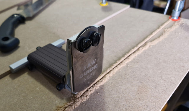
After the cut.

Using similar-sized 450x800 MDF boards on top of another, I could make a fence for moving the guide smoothly and check the 90-degree by aligning the top board as close as possible. This works only if the boards have been cut accurately enough in the factory!

However, my first cut didn't really succeed. From the ends, the piece has the correct measure, but something happened near the middle, resulting in a long curve, deviating about half a millimeter.

I had a few ideas of why it happened. The third one is the important one.

Firstly, I may have pulled the guide against the fence with too much force. After all, the fence was only clamped from the ends. This couldn't really happen inwards, but perhaps vertically, just enough to disturb the guide.

Secondly, sawing ahead of the guide can result the blade veering just a little bit, and from that moment on the board itself can force the saw into misalignment that's neither easy to see or correct. If everything else is right, speed in itself shouldn't matter all that much.

Left: wrong. Right: right.

Thirdly, and most importantly, I sawed with a too steep angle. Using a lower angle should create more surface between the saw and the guide. This also makes the cut in the board act as a better guide. The saw point where the "decision" is made is closer to the guide midpoint.

For the later cuts, I tried to keep the angle low, adopted a routine for moving the guide, sawing as much as by ear as by eye. I tried to hold the guide in place, only pulling it gently and checking it is firmly against the fence.

It is important to have a good, comfortable position from where you can also see the saw alignment. The blade shouldn't bend at all against the guide.

The later cuts were about as perfect as I could hope for.

Measure and mark, use the dummy plane, dummy.

Repeats, as I've already observed, are not very simple to do with these guides.

Ideally, there would be a jig for making similar cuts without measuring each piece separately. But for that I'd have to build a rather large jig.

Fortunately I think it is enough for most cases to do an accurate marking and measurement, and use the dummy blade to simulate the cut. You have to choose how the dummy is placed in relation to the marked lines, and be consistent with this choice.

Errors might compound if pieces are sawed off from the same board, and the new measure is each time marked from the previous cut. The pieces could end up correct width but no longer precisely rectangular. This compounding should not happen if the fence can enforce the 90 degree angle for each cut.

Drawing all lines for all cuts beforehand isn't viable, as the blade thickness is difficult to factor in.

With these techniques I began to make a 38x220x89mm box using MDF slices from 800x450 boards I ordered. (The box is intended to fit a 19 inch standard rack, taking two rack units.)

Spot the mistake

The plan for sawing the material was made in Librecad. This doesn't take into account the saw thickness, so it is just an approximation of whether the material is enough for a box.

After the shaky start described above, the rest of the wall pieces were accurate.

I glued the box together using four Wolfcraft (that brand again) corner clamps and two Cocraft clamps. As the wood glue doesn't dry instantly, there's some time to adjust the corners. Much like with artists' oil paints, the slow drying is a feature, not a bug.

The corner clamps are more for keeping the pieces up and do not itself produce an accurate position.

Corner clamped

Although the Cocraft clamps only give a gentle pressure, without them the box would fall apart.

The bottom was then glued and held together with six small clamps.

I was initially well pleased with the box. But, considering the box was intended to fit a rack mount, I had made a crucial mistake.

For some reason what was meant to be the outer dimension (438) had become the inner dimension and the box ended up being 450mm wide instead of 438. This mistake was made early and I had ordered the MDF material already in wrong size.

Corner clamped and glued

What's even more unfortunate is that I'd already added reinforcing pieces to the inner corners of the box.

I pondered if I should simply build another box, but I couldn't foresee any use for the wrong sized one. The Z-saw guide and the saw came to the rescue. I cut away the ends from side and yanked them off using a clamp as leverage. Then I cut 3mm MDF to size and glued them to the ends.

The end result is not 438mm, and not as clean as the original box, but at least I can continue prototyping. Some day.

Saturday, 31 August 2024

Wolfcraft flip-bit system

The flip-bit attached

Sometimes I just see something and know that eventually I'm going to buy it. A flip-bit system for power drills. More toys.

The idea here is that you can attach two bits, drills and such to the flip-bit and then it should become handy to switch between the two. Two flip-bits can have four functions at hand. If this sounds a little silly, well, it kind of is and isn't. Read on...

Wolfcraft 3086

I confess I somehow thought the bits would flip magically while in place, but that would be far too magical. You yank the flip-bit out of the locking position, pull it out, turn around and turn to lock.

At first the flip-bit didn't seem fast and I felt I had paid for things I already owned.

Also, this is more for garden bench type tasks, perhaps for someone who doesn't have many tools to begin with.

For these reasons, my first impressions were not all that great, but after using the set a few times I started warming to it.

The flip-bit pieces, with bits attached

The bit that does a drill hole and the countersink hole in one pass, is already of some value in itself. The short drill bits act as they have a built-in depth limiter, and these have their uses too. 

Although I must also point out there are situations where the drills might not reach deep enough. Another downside is you're stuck with the 2,3 and 4 mm drills as normal drills are too long and can't be attached to the system.

The flip bit gimmick requires some more forethought than I usually do, but that can only be a good thing.

I have to figure out what I need for the task, for example attach the countersink+drill into the other flip-bit, tighten it, then insert the relevant screw driver bit to the other side.

Countersink tools and a bit for e.g. screw hooks.

The sides are not symmetric, so you can't attach two drills to the same flip-bit. The driver bits are attached magnetically, while the other side needs to be tightened using a hex key.

After drilling the holes I turn the flip-bit over and re-insert it.

This isn't so much about speed. You can learn to switch bits quickly by holding the drill chuck and using the motor to remove/attach them. At least I don't have to fear dropping and losing small parts.

The whole kit

Usually, a second power drill comes in handy when doing multi-step tasks such as countersinks. But the flip-bit largely removes this need, and there's less to carry around.

The positive sides outweigh the few constraints. The flip action isn't perhaps all that great in and of itself, but the set brings together some order and intelligence. It would be wise to keep these trinkets together in the box they came in and not mix them with other gear.

Sunday, 7 July 2024

Z-Saw guide "Best"

Saw, guide and clamped piece in place. Angle ruler just for scale.

Quick on the heels of the Z-saw guide "F" I also got this simpler guide, intended for 90-degree and 45-degree cuts. It also promises to help with parallel sawing.

This is smaller, but it's still quite heavy and the instant appearance is that of robustness and high definition.

It's not simple to claim 90-degree accuracy, and I'm not sure if I can ever expect perfection from something like this. For example, there are more expensive try squares that do little else than verify an angle.

Here the removable guide part is more clearly positioned to the the side of the tool than it was with the "F" guide. I feel more confident about that detail. 

Small but effective.

The guide part itself is smaller and thinner, and I'm not certain it wouldn't sway under the forces hand sawing can produce. It's only secured from the top with two adjustment screws.

Even the first time I could more easily do a 90-degree cut. But I also saw ever-so-slightly lopsided result with a 21x45 profile board – better results may require some experience and the right "touch". But at least while sawing 21x21mm profiled rods, I encountered no problems.

There are two blade thicknesses, and switching between the two means altering between two guide parts, which can be hand-screwed loose and re-inserted in desired order.

The other thickness is the same as with the "F" guide so I could use the saw supplied with that guide and attach the smaller blade with the grip that came with this guide.

The guide plate in place, the angle ruler just for scale.

From the manual it looks like I could just press the device against a wood piece and cut. Hence the rounded "handle". I much prefer to use clamps.

It's actually possible to remove the handle part, giving a more straight surface for clamping, but as it doesn't make a huge difference I left it on. Who knows, the pressure might be better distributed when it's on.

Again, doing repeats has to be figured out by other means.

I set a reference rod side by side with the work piece using a try square, while clamping them together. Then I inserted the dummy blade to the saw guide, pulled it down against the reference and clamped it to position. This needs to be done carefully as the dummy blade bends easily.

Pulling the guide dummy blade against the reference rod end.

This way I could get the length to the territory of less than 1/10th of a millimeter accuracy compared to the reference piece. This doesn't sound that bad but actually is rather annoying if you really need the pieces to be of the same length.

For my practical case this was ok, as gluing and clamping resulted in more inaccuracies than my sawing...

But I could do better by using a dedicated stopper. Also, it might be better to rely on something else than the dummy blade.

For the modest gate-like object I'm making, I needed to have 9 equally long rods with preferably no deviation from the 90 degrees. The method I used, this tolerance was bearable and I was pleased enough with the result. Especially the angles appeared to be smooth.

Another way might have been to clamp together multiple rods at once and attempt parallel sawing. Perhaps another time!

The Best saw guide is easier to use for this task than the "F" guide. I'll look into doing the 45 degree cuts later. Is it exaggeration to have both? Perhaps not, as I have no other silent options for making cuts.

Nice enough!

Friday, 28 June 2024

Tool Time: Z-saw precision saw guide F

Piece clamped into position, the saw in place.

Decades ago, as a naive young man, I bought the cheapest possible plastic mitre box and assumed I could easily create wooden frames for paintings. Didn't happen.

Decades passed.

Now, Facebook ads, of all things, pushed this device that might be the ultimate compact hand-sawing assist. It's not one of those space-eating mitre saw contraptions, here the saw blade passes through between aligned metal plates. It's fairly small and should also help in longer parallel cuts.

Apart from that the guide does any angle, compound angles, it's quite easy to apply and the cut is precise and even.

The dual adjustment for vertical angle.

Adjusting the device is a little trickier. Although it's heavy and sturdy, there's no immediate "lock" for accurate 90 degree position. Sure, there are markers but these are far from the kind of definition you'd find in a vernier caliper, for example. For the vertical alignment, two adjustments are needed. 

Just eyeballing the markers isn't enough to ensure proper angle. Either you use the scribe-dummy plane-cut method as described in the manual, or you calibrate the angle against a smooth surface with a really good try square.

The device is somewhat lacking in surfaces for doing such a calibration. The vertical is easy to set, as there's a lot of surface to put a try square against. The sticker is somewhat in the way, and this is a good reason to remove it.

Calibrating the guide vertically. Here still trying to avoid the sticker.

The horizontal is harder to set, as there's even less surface to work with. But it's possible to lower the guide portion below the table surface level, and "pull" the backside of the guide against a corner of a piece that's known to be 90-degree accurate. (Easier said than found...)

All in all, I believe the guide is meant to support the scribing method described in the manual. So, everything needs to be checked before committing to a cut. The process can be either meditative and interesting, or just frustrating.

Calibrating horizontally against a corner.

Two additional items were included in the set, intended to help identify the correct angle. One is an angle protractor. It is a minimalist item, but testing it against a try square it does produce accurate angles.

The second item is a "dummy plane", a .6 millimeter thick bladeless plane for verifying the marked line and adjusting the guide into place.

The whole circular guide element can be moved vertically, by releasing the knob. This is more essential for the angled cuts, but even with a straight cut it can be useful to drop the guide against the piece as the sawing proceeds.

Some of the extras. The 90-degree guide is attached.

There are also a couple of attachments, a removable handle and two guides. One guide helps with parallel sawing, the other is for cuts. With long parallel cuts, it's expected the saw guide moves with the saw as the cut advances.

I'm not super confident about the guides, as their placement appears slightly less than absolute. I'd also recommend using two clamps rather than one, when attaching to a piece.

A variant of a kataba-type saw (backless, thick, general purpose) is included with the set, and as is with these Japanese saws, it operates by pulling rather than pushing. With the way the guide works, a backless saw is a necessity.

The grip is removable and can be attached upside down too.

Another angle, showing the adjustment key at its home.

A sore point here are repeats, which the device cannot really solve on its own. You'd need a fairly extensive jig/guide to be able to do both adjustable and repeated parallel cuts.

There are nice details, the T-shaped allen/hex type adjusting key has a home inside the guide, and it's best kept there when not needed.

Like I said the ground plane of the guide is sturdy, in addition it is easy to attach to tables and other pieces using clamps, especially after removing the handle (not pictured) out of the way. The plane also has enough holes to attach it semi-permanently to a jig.

Result.

A good try square is needed to test if the result is properly 90 degrees.

I won't pass a full verdict now, as the pieces I've worked with are not that precise to begin with. But it does seem some attention is needed to get best results. I could find some lopsidedness in one corner, but for most practical purposes, the wood end is as good as perpendicular.

All in all, I'm more positive about this device as I gain practice. For anyone who has access to electric saw, it might seem slow, but it's better and faster for the job than anything I've had before.

I likely wouldn't recommend this guide on very thick pieces, and some reviews seem to suggest as much. It's logical, the more the saw comes out from the guide, the more potential there is for drifting. 

For my purposes a guide with a rigid 90 degree angle might have been more useful... and I did actually get another, simpler guide. It's early days, but both seem to have pros and cons. More about that in another post.

Tuesday, 18 June 2024

Tool time: Incra rulers

The Incra set (they have many more models)

Marking/scribing rulers have come some way since I last checked. These are laser-cut, laser-engraved, with built-in templates accurate to sub-millimeters. Although not cheap, they are not dirty expensive.

The straight ruler is the most boring one, and I can imagine only very few necessary uses for it, so I won't focus on that as much. As a part of the set it has a purpose so I don't mind.

The bend ruler markings are only accurate to a millimeter, but the other rulers have a 1/4mm granularity, achieved with rows and rows of offset tiny holes. Here the bend ruler can be complemented with the straight ruler, should more precision be needed.

Bend ruler

The bend ruler, which could be called a saddle ruler, is useful for marking around the corner of a small piece. The end part also helps in scribing parallel to the piece, and finding the centre.

The bend is not in perfect 90-degree alignment, and you have to push it rather firmly against the piece to get results.

The T-square is the most interesting of the lot, and perhaps most versatile. Obviously a straight edge is needed to begin with.

T-Square with some blemishes from my sweaty fingers

The T-square had to be assembled, which made me worry it wouldn't be accurate. However, the parts connect firmly enough. 

Testing the angle wasn't as easy as with a normal try square, as this doesn't work when flipped around. A rudimentary test with marking lines from opposite edges of a machined chipboard looked it would be precise at least in these distances.

To find a centre, it's better to trace from both sides rather than trust a direct reading. This is very simple to do with the Incra T-Square.

Finding the centre from two directions, using the 10mm slot.

A suitable pencil was supplied with two of the rulers. It's worth noting that scribing and marks require some composure and practice, it's not entirely automatic. The pencil tip might be uneven and result in slight inaccuracies.

It may be helpful to decide which side of the hole you press the pencil against, to have more uniform results. I didn't get any problems really.

Some of the ruler positions have slightly diamond-shaped holes, which I guess would help in making the trace more accurately.

The macro lens adds some fish-eye here, the ruler is obviously straight as a rail.

Although these rulers are probably mostly intended for high-precision woodworking joinery. I make rather modest boxes, as can be witnessed from my blog. Even then the added accuracy can help, so they are not going to remain unused.

These rulers are metric, but for through-hole electronics related tasks an imperial set might make sense.

For just doodling around the set would be somewhat expensive, but not as expensive as Woodpecker T-squares. Although I have my eye on some of them too.

Another macro shot, detailing the pencil head connecting with the ruler.

In woodworking it's often more desirable to use repeatable settings and jigs, rather than following markings one by one. Drawing the intended cut and then cutting it, can result in a poor procedure. With hand tools you might not have a choice, though.

Oh, and a ruler can be called a "rule", giving rise to the "Incra rules" pun on the rulers... but perhaps they do?

Thursday, 14 July 2022

Tool time: Drill guides

I got a drill guide and a doweling jig, after a situation where these might have been useful. But I can at least blog about them.

In the past I have managed with drilling through a wooden block and using that as a guide, but these ad hoc pieces easily get lost and mixed up.

When ordering from the internet, half the trouble is knowing the Finnish words for some items. Again, when writing this blog, there's the added trouble of finding the English words.

So:

Wooden dowel pin : Poratappi
Drill Guide : Porausohjain
Drill Stop/Depth Stop: Poraussyvyyden rajoitin(!)
Dowel joint: Tappiliitos, Poratappiliitos
Doweling Jig/Dowel Gauge : Tapitusohjain
(Dowel drill) centre point : Tapituskeskitin
Hex key/Allen key/Allen wrench :  Kuusiokoloavain

Often Google Translate can't figure these out correctly, and the terms are not certain to begin with. According to GT, tapitusohjain is "Tap Controller", and poratappi is "Drill Pin".

Looking at item lists of complete doweling kits was the easiest way to reveal the terminology.

Dowel joints aren't exactly the state of the art, but they can be done at home without huge tools. At least somewhat precise positions and 90 degree angles are needed, so guides like these can be handy.

First, the Wolfcraft Dowelmaster jig:

This jig has an adjustable/removable block that helps position the jig against an edge. Then I can drill 6mm holes through the device.

The drill stop is almost necessary for preventing accidentally drilling through the material. The stop is tightened in place using a tiny Allen key. It did keep falling out, though, it would work better on the non-bladed area of the drill.

At this position drilling the right hand side was rather easy. To make a 6mm hole at the left side was trickier because the tool can't be mirrored. (The holes are for 6, 8 and 10mm pins respectively)

Drilling the holes through the edge was little harder, it would be helpful to have the piece attached somewhere.


As can be seen my test joint is not very precise. But the result was ok considering the wood was not very even or cut very accurately, I wouldn't blame the jig here.

The idea of keeping the device at place with your hands is fast, but also kind of crap. Especially here when working with small pieces I kept trying to find a good position.

There are more straightforward jigs that can be clamped to the piece. But the Wolfcraft jig has a few tricks up its sleeve. The contraption can be held diagonally against the edge of the wood, the edge held firmly within the "X" shape of the jig. There are two ways to do this depending on the thickness of the wood. The pinhole position can't be adjusted but at least the holes will be equidistant.

I liked the simple drill guide. ("accumobil Mobile Drilling Aid") It's not specifically made for dowel pins, but it does have the 6,8,10 sizes.

The device is better used upside-down, because what looks like the top works better for the special cases of drilling into a corner or a round object.


There are also marker lines around the guide. If you want to use them you have to mark your boards very generously because otherwise they are not very easy to see. 

Here the wooden piece is so small I couldn't even check the lines from all directions. It may be a better to make ~2mm deep initial drillhole and then finish the job with the guide.

Here I also made use of the drill centre points, these small metal pins.

The idea is that the drill hole positions don't need to be super-precise. Drill holes into the first board, then put the centre points in the holes. The second board (edge) is pushed agains the pins and the drill locations will be correctly marked.

For the edges, I again used the doweling jig, and I wasn't very comfortable with it but the result was fine. It would work much better if I had gone through the trouble of clamping and positioning the parts with more care.

So, altogether these felt robust enough for my purposes.


Addendum 15.7.2024: Having used the Dowelmaster more it worked fine enough. The adjustable fence is ridiculously low compared to some similar models I've seen. In some situations this may save space but here end-wood doweling felt risky. The weird shape of these objects can prevent creative clamping. Also, adjusting the position would be easier if the tools were more rectangular. I checked the clamped position using a light, peering down the jig hole.

Friday, 29 November 2019

Crafting chesspieces


Barleycorn is a common name for a highly ornamented, tall red and white chessmen, elevated on an urn-like pedestal.

One might think the name 'barleycorn' has something to do with the tallness or shape of the pieces, but apparently it refers to the decorative barleycorn leaf motif found on them. So whether a set without the decoration is truly a barleycorn chess set I can't say. But it's a handy keyword for searching a certain type and I'll use the word here loosely to describe mine.

I've longed for something like this, but barleycorns are quite expensive (200 EUR easily for a modest, complete set) so I started thinking whether I somehow could build my own, even if it wouldn't be as decorative.

I don't have a lathe. The main idea was that the pieces could be created by fitting ready-made parts around a central stick, like beads in a string. Visiting a few hobby shops, I looked for ready-made wooden parts that could help in this.


First phase

After I discovered a part that would work as the base for all pieces, I was already more optimistic. I felt a larger set would be more forgiving for inaccuracies, so I chose a 35mm base. As barleycorns tend to be placed much more tightly than any FIDE regulations now say,  a 50mm squared board should be good for these.

I didn't give much consideration to finding larger bases for the King and the Queen although it is clearly a feature of the barleycorns and most chess sets.

Is it a chesspiece or a sci-fi rocket? Here the barrel is cut and filed out of a cube.
I bought a bunch of the ready-made wooden parts I could find from hobby shops, trying to figure out how they might be used together.

After having a pool of parts, it was time to scavenge more definite images of barleycorn-type chessmen from the internet. I did not seek to replicate any one set in particular, instead I picked features from different sets that I liked.

Of course it was important that the details could be recreated with my parts pool. It was a relief to find out not all barleycorns are especially decorative and I could take that as a guideline.

I needed to ensure the 16 pawns would not require much manual work. I'm happy to note this stage was quite successful, as the pawns are the simplest part of a barleycorn set in any case.

Left: a nearly complete queen, Right: demonstrating the stick-system 
Each pawn and piece has a narrow stick as a central axis. This meant drilling parts that didn't yet have holes in them. Especially the pedestal part required some care as it's not easy to drill into a convex end.

All the collars needed drilling too, finding the dead center was a bit tricky. The small brittle pieces break easily when drilling. For the tiniest collars I just had to patiently drill 1-millimeter pilot holes before making the 2,5 mm holes.

Sample of the parts pool. Note the absence of holes in many of the parts.
In the beginning I made many mistakes, often compounding so that some pawns were unacceptable and had to be remade. Poorly supported parts may move as a result of the glue drying process, which I also forgot to check.

I built a drilling jig out of a wooden block which helped in getting the holes more accurate. This became necessary as I noted I really have only so many bases and 32 perfectly drilled bases are needed.

One trouble I had that there really were no parts for inverted curves (e.g. the "scotia" in antique pillars). I emulated these by using a combination of different collar pieces.

With all the easy labor behind me, I begun work on the knight horse-heads. Here wood putty was somewhat useful as the shapes could not be cut very precisely. I was not overtly happy with the knights, but I needed to make progress on this most difficult part before my enthusiasm runs out.

And run out it did. After I finished the four knights and whittled one bishop head, it took a better part of a year before I could find it in me to continue with the set.

Carving the bishop-heads. The white colour is from gesso primer.

Second phase

With renewed zeal, I sat down and whittled the 3 missing bishop heads and started planning the rooks. Here I drew more accurate sketches, because I had lost the sense of the project and the proportions. The rook designs had been previously unsolved, but I had decided they ought to be elevated. (Less common in barleycorn sets but it has been done).

The drawings were useful in finding the proportions for the rook although in the end I improvised some choices.

The tall rooks ought to go without pedestal really.
Instead of forming the rooks out of solid wooden blocks (my first plan) it struck me that with a proper cutting tool I could create the rooks out of 4mm plywood circular plates.

I had seen such a tool a while ago and now I bought it. It's meant for cutting holes into drywalls and the like, so the cut-out is not really the intended product. But it worked well enough with the power drill and the 4mm plywood. The resulting edges were somewhat torn, but filing and sanding them together I got them quite smooth in the end.

I tested each plate size to find out what my options are and then redrew a rook design on a millimeter paper using this knowledge. Only the center part would be cut out of the solid blocks. Cutting dozens of plates was a bit boring, but likeable procedure.

Measuring plates. The leaflet only supplies the hole inside dimensions!
With this tool the central drill was 6mm fixed diameter. This was helpful for gluing the plates together around a 6mm drill bit, but as the 6mm hole was not suitable for the narrow central stick, I also needed "converter" parts. I won't explain this in more detail.

I used the plate-approach for creating the royal pieces too. I was unhappy with my earliest ideas (see the first picture) and chose to do a simple straight barrel that probably looks better.


The outcome

There is something cartoonish about the designs, especially the rooks are very huge, much larger than the base they are standing on. This is not something I've seen in any set, as the rooks usually are not elevated, and when they are they certainly do not exceed the base dimensions.


So I could also make some original choices. Possibly I also felt this cartoon approach gives the set more character than a failed attempt at copying some existing design.

I did not plan the whole set before looking at it all together so it was fortunate the pieces work together as well as they do. But even during the process I could match certain pieces to work together, so it was not all done blindly.

The set is not especially heavy. The king and queen are sufficiently weighty, but the pawns and other pieces are somewhat light and unbalanced. I could help that little with leveling the base bottoms a bit.

Board supplied by Marq, a nice fit.
Small amounts of pieces in plastic bags turned out to be quite expensive in total, so it's very likely I could have instead bought a somewhat battered antique barleycorn set off eBay with the sums! Well, it's more interesting to try to make your own.

There is still some painting to do, and I'll do more close-ups when the finishing has been done.

Sunday, 23 December 2018

Chessboard modification


I received a 30cm chessboard box that was in a slightly poor condition. I have a better box in better shape (pictured above) so this was an opportunity to modify the damaged one.

The set is nostalgic for me as I played with similar pieces a lot during my childhood and youth in the 1980s-1990s. I believe these sets and likely the design itself originated somewhere in what was then the Soviet Union, and come in numerous variants and varying build quality. I have no idea how typical these might have been over there.

I am especially fond of the bishops, with no distracting "mitre" or knobs on them.

Admittedly the board is a bit dense for playing, although it looks visually pleasing to me and given the history I'm hardwired to accept this as a normal chessboard.

A board with slightly larger squares could still come handy. The goal at first was to increase the size of the playing squares, but I also became quite interested in the surface treatment.

Half board removed. The amount of dust is spectacular.
The box is 300 x 300 sized, with the original borders it makes the effective play area about 280 x 280 with 35 x 35 mm squares.

To fit this more with my blog theme, I used a Commodore 64 BASIC loop to calculate the measures. So, without the borders the square size becomes 300/8=37.5


The box is slightly deeper than it is wide, so I used 151.5/4 to get the other square dimension for each half-board, which was 37.875. Although this kind of precision is somewhat pointless for my handiwork, it is important for adding up the cumulative measures.

Sanding away the existing squares was the most boring work stage, although the actual sanding likely didn't take much more than 30 minutes altogether. The staining and lacquer treatment requires the surface to be well finished, and I used 80, 120, 240 and 320 grit sanding paper to get there.


Woodstaining

The measure marks were made to all edges of the board, then I used a paper knife along a ruler to pull grooves across and along the plywood. This means that when I brush in the dye, it won't be absorbed over the square edges.

Carefully testing the board, the pieces don't touch the stained parts yet
Still, the brushwork needs to be careful. It was better to allow the liquid to flood towards the edge instead of trying to brush directly along the grooves. Firstly, the absorption effect is quite forceful, and secondly, the brush could also easily touch the other square which would be "goodbye, board" to me.

The cuts across need to be quite deep whereas the cuts along can be shallow.


Lacquer

After letting the staining dry overnight, I applied urethane alkyd lacquer on the surface. One layer of the lacquer was nearly enough to make the kind of smooth surface I looked for. After 24h drying I made a light in-between sanding with the 320 grit paper, wiped out the dust with a moist rag, waited a bit and added another layer.

But after half an hour I dared to test the whole set. (This is still without the lacquer)
Afterwards I'm quite happy with the surface. I did get those tiniest bubbles for both layers. This might be unacceptable in a continuous table surface, but with this kind of checkered board it is not too visible. If you look for them they are there.

Can the bubbles be avoided? It turns out I had not heeded the instructions: the first layer ought to be thinned by 20% and multiple thin layers would be better than 1-2 thick layers. Also, a proper brush might have helped reduce the "bubbles".

Comparing the new width squares with the old.
The paper knife technique has the weakness that the grooves will remain visible. More often than not paints and lacquers tend to highlight scratches, dirt and unevenness, than smooth them out. Still, I don't think these grooves are ugly.

An alternative approach might have been to make a new board layer entirely from plywood and glue it on top of the existing one, this way I could have avoided the sanding. But it would have been a different project.