Showing posts with label midi. Show all posts

Wednesday, 31 July 2024

Akai EIE (not Pro)

Akai EIE

I never really had a solution for simultaneous multi-track recording on the computer, so it's high time I got to experiment with it. I got this old AKAI EIE for so cheap it doesn't much matter if it disintegrates tomorrow.

The EIE is from 2011 so it's a little long in the tooth. Technically, I can use the likewise old Fostex MR-8 to record four mono-tracks, but it is a cumbersome solution and I don't even really have the cables to do that.

By the way, it's easy to miss the distinction between the EIE and the EIE Pro version. They have the same interface, but the Pro version has higher sampling rates available. The pro has a silver panel, whereas this older EIE has a red panel. The mistake is easy to make, after all the word "professional" is stamped around the box about four times.

This is in a way fortunate because the ordinary EIE does not have any complications with drivers on Linux, and I could quite happily record 4 simultaneous tracks on Audacity on first try. But the quality remains at 16bit 44Khz.

The front panel

Before relating my experiences, I'll have a peep at the panels.

In front, there are the four inputs, combo XLR/TRS style, four gains and settings for guitar/line/mic levels and phantom power.

There are two round analog VU meters, which contribute to the somewhat naive styling of the box. The late 00's saw these weird retro aesthetics on synths and gear. Hence the analog amp look, replete with metal toggle switches. Usefully, the VUs flash violently red if peaking. In a dark room you'd probably see the flashes even if you weren't looking at the VUs.

Volume Unit meters

Some further knobs and switches adjust the headphone level and channel combinations. There's a toggle for stereo/mono which is useful when recording mono channels. You can also decide which channel pairs are shown in the VU, or if they indicate input or output.

At the back there are four outputs and inserts, and apparently the inserts can be used for external sound processing. Without a bus and level adjustments (it's not a mixer after all) I'm unsure what is their value. Perhaps the idea is to control the levels from the separate equipment itself. The short manual isn't much use here, apparently monitor speakers can be connected to the outputs.

The back panel

There's MIDI in and out, and the main USB connection between the EIE and the computer. An 1.1 USB doesn't sound much, but it should be enough for the 16-bit 44Khz traffic. The Pro version I suppose must have USB 2.0.

The EIE also works as an USB hub for three devices, but again with 1.1. so maybe only useful as a power source. Ok, it's possible to insert an USB-MIDI keyboard.

Somewhere I read a comment saying these USBs produce very little electric disturbance and hum, so perhaps there's that too. It might be the one area where the EIE has become a little more valuable over age, as so many tiny synths can be USB-powered these days.

EIE and Ardour

I was mainly interested in having multi-channel audio recorded with MIDI-clock sync. Recording without synced clock would be nearly useless. A "120 BPM" in the source machine might not agree with the recording computer, and there would be a mismatch between the bar grid and the sound data.

As the recorder sends a clock signal, the audio will be instead happily laid over the bar grid, facilitating further bar-based editing and song construction.

I tried Qtractor at first as I'm already familiar with it, but I just couldn't bother with getting EIE to work with Jack, so I installed Ardour and used ALSA.

Ardour5

I'm not that keen to move over to a full-on DAW that does everything, Ardour looks sufficient for recording and has good editing facilities.

As I have a Roland Boutique synth, on occasions I found Linux had chosen that as an audio device (the boutiques do that) so I had to explicitly tell the system the EIE is the desired output device. Looking with Alsamixer there are no adjustable parameters for the EIE.

Ardour tracks explicitly connected to outputs

Setting up things with the EIE and Ardour had some complications, as it wasn't always obvious if I'm meant to hear the sound or not. I fought for a while with something I thought was a clock sync misunderstanding, only to find out I had to flip a switch in the EIE to hear the sound. It's a little uncertain if the same would have helped with Qtractor, but I doubt it.

Also, Ardour can lose the configuration and it may need to be re-set for each new project.

I can also have four-channel output from the Ardour but in practice it's better to re-route to "stereo".
Ardour MIDI clock setting for EIE Midi interface

Likewise, to have the MIDI clock working, I have to use the Ardour "patching matrix" style interface. Here the Boutique has imposed itself as a possible MIDI device too.

I have to say the editing is quite intuitive, the audio blocks can be cut, spliced and moved about quickly. 

What I got with my setup is a slight mismatch between the recording starting point, which didn't exactly line up with the beginning of the tracks. Not sure if this has anything to do with EIE, or some parameter in Ardour.

Anyway, it was easy to fix in the edit, by cutting the obvious extra and moving the tracks to the start position. After that it's simple to cut, paste, remove and repeat song portions.

Some empty space at the start of the recording, to be cut away

A problem with a small number of recording tracks is that separating percussion could easily take four or more channels.

There's a cheap way to improve the situation a little, by recording permutations of the beat after the "song" proper has been recorded. So you can have bars with kick or hihat only, then use repeats to create new tracks for all of them.

In any case it looks it would be better if the basic bones of a song fit into four tracks. Afterwards, four more tracks might be recorded for further embellishments. Again it looks like the gear is aimed at the classic 4-person band who want to record a demo.

Trying to figure settings for punching in some MIDI USB keyboard playing ultimately crashed Ardour, and I started recalling why I moved away from this type of software in the first place.

But anyway, in the end the EIE box did what I wanted, it records four (mono) channels simultaneously and it wasn't expensive. In addition, it does perform as a funny-looking sound card, and I don't have to switch between general computer use and sound recording contexts.

Monday, 12 December 2022

Another time, another Fostex


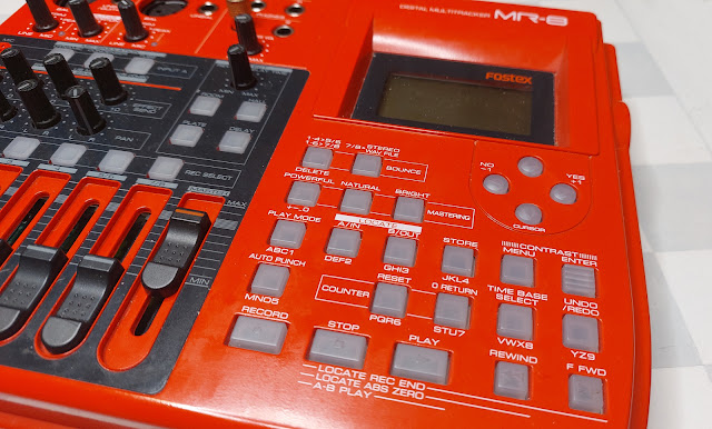
Yes, the "red one".

I did once discuss a broken Fostex 4-track tape recorder, which I never really properly repaired. I got a good impression of the Fostex brand and when this striking-looking MR-8 digital recorder was available on a net auction, I blindly hurried to get it. This already some 5 years ago I think.

After the initial excitement of having a multi-tracker strongly influenced by the 4-tracker tape workflow, I felt it was too slow and limited and the box mostly spent time at the back of a shelf. Besides, calling it an 8-tracker is really a stretch. You can only record two inputs at a time, and only four of the tracks behave individually. The 4 other tracks are stereo "bounce" pairs 5/6 and 7/8.

The MR-8 is from around 2003-2004 after all, at a time when a cheap digital recorder became a possibility but the concept was still somewhat marred by tiny memory space, slow USB and card speeds.

Now, for one reason or another I felt it might find at least a temporary place on my desk. There's something fun about listening a recording without even turning on the computer, and on occasions learning to be slower with your methods might even be helpful.


Upgrades

One motive to dig this out was that I found out there are firmware updates. I did the 1.21 upgrade and saw this would allow me to use a 2GB compact flash card instead of the 512MB one installed. Fostex had also supplied a list of cards proven to work, which was pretty nice of them. I ordered one from eBay, a Sandisk brand 2GB card. This would bump the 48 minutes of 4-track recording into a maximum of 188 minutes.

A repeat of the firmware update instructions:

After finding the MR8V121.zip from Fostex website, unzip the file within, and use the USB function of the MR-8 to copy it over to the compact flash. (The MR-8 appears as a sort of memory stick, if the USB mode is on) After this has been done, shut down the MR-8. Then hold STOP and turn the MR-8 on again. Now the Fostex should prompt you with something like "version up", and as usual, you have to confirm it with RECORD+YES. Wait for a while, and after the upgrade is done the Fostex should be again shut down. After turning it on, you should see the version is now 1.21.

A Fostex document suggests turning the "EXTEND" mode on in the Fostex before doing the upgrade, but this might be required if the card has seen some use. My card was nearly empty, and I guess there were no problems even if I didn't turn the mode on.

After upgrading there is an option for auto-delete of undo space, but I left this off for now.

After inserting a new 2.0 Gigabyte Compact Flash card and turning the power on, the Fostex offers to format the card. After this procedure there is more than 6 hours of mono recording time in the normal mode. 

The space use depends on the amount of tracks and how much undo buffer is in use. As should be, the recorder does not waste extra space when not needed. So, if you first record a few minutes to tracks 1 and 2, and then record a few snippets in the middle of track 3, these will only take a tiny amount of memory and not a full track.


Learning to fly

I became motivated to study the device and the manuals a little more, finding some neat functions I had been so far unaware of. The manual, despite having some typos and tiny language problems, is extremely clear and well illustrated.

As an example, I was originally unimpressed with the slow export procedure. You can't simply copy your work in progress using the USB connection. The tracks 7/8 are exported into a specific WAV stereo file, which in turn can be copied over the USB. Creating the 7/8 track seemed to require the re-recording of the tracks using "bounce" function.

But now I learned I don't really need to re-record to 7/8 in real time in order to export them to WAV, as I can simply "copy" tracks 1-2 to 7-8 internally, which is much faster. Assuming all the material is in tracks 1-2, that is! Then again, if I'm using all tracks I could choose to export tracks 3 and 4 to 7/8 too and combine the audio at the PC end.

Anyway, this track-copy function helped me try out different recording parameters and seeing the results rapidly on the Linux side. I also found out that most of the track functions work not only on single track, but on the 1/2, 3/4, 5/6 and 7/8 pairs which makes these tools more useful.

Also, the part copy and erase functions made more sense once I used the internal clock to synchronize a sequenced recording. This way, the recording can be revisited in Bar/Beat timing and not in seconds. I'll tell more about this below.

The sync also could help record tracks separately with accurate timing. For example, record one song element to tracks 1/2 first, then another to 3/4. An optional audible metronome click helps live play.

Using the inertial rewind and forward buttons together with the unresponsive STOP is still quirky. I could have used the good honest cursor keys to step between bars.

Things like the on-board effects processor and mic/amp simulations are perhaps better ignored, as they are not very functional and some of them are simply on-off without any parameters. It looks like everything in the device is geared towards making a simple demo for a performance that might include a guitarist and a vocalist.

For the hell of it, I also tried XLR cables for inputting balanced audio from the mixer, although with the distance of 1 meter it should matter very little what kind of cables I'm using. The XLRs ought to be used for microphones really. But in contrast with instrument cables, I seemed to need less TRIM for Input A and B to get the same volume level, which kind of sounds promising? My ears could not really discern any difference in results, though.

Opening the box

I also felt an urge to look inside the box, as some of the buttons were a little unresponsive. The STOP button and the STORE button have to be pressed hard to make them work. Yet it was clear the switch below the button "clicks" in a tactile way.

Some sawdust particles had got between the LCD and the plastic cover, and this irritated me as the screen's not that big anyway.

Pull out the faders first. The knobs do not need to be removed.

Do not remove the "foot" screws and the "battery compartment" screws. Screws near "Digital Out" and possibly MIDI, do not need to be removed either, but I did take out the latter. (Edit: These do not need to be removed.)

There are screws at the bottom and back that need to be taken out. The three bottom screws near to the back connect to a metal plate that needs to be detached later. These screws are somewhat longer than the other. (When putting these three back, put them loosely in before tightening them fully, otherwise one of the holes may be mismatched and it will be difficult to fit.)

Then the red cover should pull out together with the LCD and the fader/button unit. After disconnecting the mic leads and the two ribbons, the parts can be pulled out entirely. I found it easier to unscrew the mic rather than try to disconnect it from the circuit board.

Then, more screws need to be taken out to detach the LCD/fader unit from the plastic cover. There's also a protective "silver cardboard" which probably does little or nothing to remove interference.

After cleaning any visible dirt and putting it all back together, the STOP and STORE button did not become markedly more responsive. Possibly the switches have become worn out. I did manage to clean the space between the LCD and the transparent cover, so there are no longer any particles there.

Possibly, to repair the buttons I'd need to replace the microswitches on the circuit board. They did not appear in any way loose, and the one-piece plastic contraption containing all buttons didn't look damaged.

5.2.2023 Edit: I took a closer look, and re-soldered the tactile switch connections while pushing the switches closer to the board from the topside. This improved the connection and the STOP/STORE buttons now work with lighter touch. The switches are 6.2x6.2mm with top measured varying at 4-4.5mm because of the way they had been soldered in. With only two pins as the poles it would not be surprising they might come loose easily.

MIDI clock-based recording

The Fostex has a MIDI out port, a feature I had not previously used. I recall this caused some initial confusion in me, why does a recorder have a MIDI out port? But it's actually rather obvious. The port transmits the MIDI clock to a sequencer and it is possible to make timed recordings this way.

A song can have a tempo and time signature map, so the Fostex is not limited to one overall speed or time signature. After making these selections and recording a synced track, it's possible to switch over to the Bar/Beats notation instead of the hours/minutes/seconds timing.

There are even two kinds of sync methods, the simpler MIDI clock and the SMPTE/MTC. I used the simple clock, and it looks like to me for recording a complete song it should be sufficient and uses far less MIDI bandwidth.

The simple MIDI clock sends start/stop/continue signals and a continuous "click", all using single-byte signals. 0xFA for start, 0xF8 click, 0xFB is continue and 0xFC is for stop. Other MIDI message contents are always seven-bit, so even if a click arrived mid-message, it shouldn't be difficult to parse. 

For a 4/4 time signature, the click byte is sent 24 times for each quarter note, giving a resolution of 96 for one beat. 

Frankly, the alternative MTC format looked rather complex, as it sends portions of the time stamp little by little. The sequencer may even need to interpolate these and "lock on" to the signal. The plus side is that it becomes possible to start the playback from any location. In the simple clock mode the Fostex doesn't send the SysEx for song position. On the topic of MIDI timings I used Francis Rumsey's book Midi Systems & Control, 2nd edition, from 1994.

When the START signal is sent (by pressing Play on Fostex), Fostex can be told to wait for a couple of empty bars before the click signal begins to roll. For my sequencer, this handily means the MIDI data can be rendered and linearized for playback, which can take a tiny moment. As the sequencer receives the click, the virtual playhead is advanced and MIDI out signals are sent to instruments.

After pressing STOP on the Fostex, the click is no longer sent and the Stop byte is send via MIDI. This can tell the sequencer to stop worrying about the incoming clock, or something.

One obvious use for this when importing the Fostex-exported WAV to a Sequencer/DAW, here for example Qtractor. After setting the tempo I have the track laid out according to plan.

Working with the bar/beat model, it's also possible to make better use of the Fostex Part erase/copy/paste functions. Usually the A and B positions are meant for working on a song position, such as re-recording a portion with multiple takes. Here the A->B positions signifies an area to be operated on a single track, and they can "snap" to beat resolution. This way I could remove a few bars out from a track, or even extend the song further by copying more material to the end.

Also, I recorded separately a bassline to tracks 1/2 and percussion/other stuff to 3/4, from the same song, and the result sounded pretty accurate to me.

So in theory, a song can be constructed using already recorded short elements. This might be silly in this time and age, but as a zen exercise in patience, it might just spur someone's creativity.

Wednesday, 16 November 2022

Korg Nu:Tekt NTS-1 ma:SSaKred

128mm wide, 78mm deep, 17mm high (excluding controls)

I got this about 100€ tiny brick of a synth, Korg NTS-1, or Nu:tekt. You build the case yourself and it has that rugged circuit board aesthetic. There's also promises of customization, both in hardware and software.

So, is this the Arduino of synths? Well, yes and no.

Yes, because it can be modified, and there are pins for accessing inputs and outputs. Yes, because it is very tiny. No, because the software architecture uses uploaded modules and it is not as "open" as an Arduino is. Yes, because you can also compile your own modules. No, because there's not a huge row of pins to access every meaningful aspect of the synth.

NTS-1 is not unique, there are several build-yourself-a-synth models around. The self-building aspect is at least partly a gimmick. But it's a nice product idea, potentially bringing the cost down a little. NTS-1 was really simple to put together with the instructions, no soldering or extra tools were needed. I used a somewhat larger screwdriver than the one supplied.

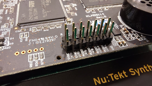
There are a few pins and soldering points that can be used to expand the synth. MIDI, audio and the sync clock are present both as ports and on-board connections. The real changes to the sounds and functionalities are done through uploading different modules.

I had somehow thought I could also use Nu:tekt as a MIDI-controlled adjustable filter, something you don't see that often. To my disappointment the audio-in is diverted to after the filter, and you can only select whether you want mod/delay/reverb affect your audio input.

But this is not the end. It is possible to upload new oscillators, modulators, delays and reverbs via the Librarian app. So I could add third party filters from DirtBoxSynth just to fix my grievance. This added some ~€10 to the cost of this device. Whether these filters are as good as the fixed ones, I can't vouch for.

The Librarian app

I also learned the architecture is shared between Korg Prologue and Minilogue, which means there's a wider market for these modules. Not all modules might be applicable for the context of NTS-1.

The Librarian app is only available for Mac and Windows, but fortunately it worked well in my 2012 Mac. A glance at the coding side makes me feel it wouldn't be impossible to compile my own effect (there are tutorials and examples) but it's doubtful I can do the math for anything useful.

Apparently an imported module only fits a particular category, so you cannot upload "bitcrusher" to Delays or Reverbs, it has to go to Mods. If so, I cannot choose to chain the DirtBoxSynth filters with the bitcrusher, it's either/or, because both go to Mods.

Ok, let's look at the more physical side of things.

The headphone is at the other side

The boards and the elements are meant for constructing the default box, so it's not a set of legos. Still, the process is nearly reversible and you are not stuck with the box you built. It should be easy to remove one of the four 1mm side panels, and replace them with your own, for example.

About that "nearly reversible". Because the instructions said so, I cut off the four screw holders from the board corners. As far as I see now they do not need to be removed when making the standard case. So, be aware when building the case you are making a permanent change! 

The controls are integrated to the top panel, which doesn't look too simple. The ribbon keyboard input connector looks a little tricky, attaching an alternative keyboard is probably not going through that route. Either find out what the pins between the top/bottom do, or use MIDI.

Header pins and four screws keep to cover in place.

The NTS-1 has no patch storage, but this is a minor inconvenience, considering all parameters can be transmitted via MIDI Control Change messages. There are Oscillator, Filter and Envelope types, with A and B parameters for each. On top of that you can have Mod, Delay, Reverb, LFO and Tremolo. There is also a rather full-featured Arpeggiator.

Like all the audio and sync ports, the MIDI port is 3,5mm one, with tip-ring-sleeve arrangement. So one of the first customization decisions might be whether you need an adapter cable (be aware of Type A and Type B) or build your own full-size MIDI port using the solder points inside. This is what I did, not long after putting the thing together.

The USB also connects the device to your computer as a visible MIDI device, so whether you even want to use the MIDI port for connecting is up to you.

Adding the full-size MIDI port

The box was even easier to open than to put together. The front or the rear panel needs to be removed before the circuit board can be lifted out.

After removing the board it is easy to access the through-holes for MIDI, AUDIO and SYNC. Note that 5v and 3.3v can be drawn from here too.


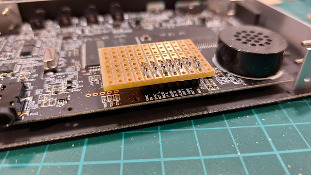
I soldered in a header strip for testing. Then I realized the jumper cable heads would not fit under the cover, so I instead added a tiny layer of prototyping board. A ribbon connector might have been helpful here.

This way I can solder/de-solder wires should I need to change them. I wouldn't want to heat the actual Nu:Tekt board too many times.

The MIDI in "tip", "ring" and GND("Sleeve") need to be connected to a MIDI DIN-style connector.

I soldered the wires on the proto pads, as it was too tricky to nudge them from the underside after the board had been fit to place. There's one more layer of that header strip keeping the board higher.

I could have soldered the wires beforehand from the more correct direction, though.

Internally, MIDI channels are 0-15, in hex 0-F, whereas software and documentation refers to them as 1-16. This discrepancy sometimes rears its head and creates confusion, but I've become used to it.

How to change the MIDI channel? Consult the manual. Plug in the Korg and press REVERB at the same time, you get to the parameter menu. Find the parameter CHL with the Type knob and change them using the B knob. Push ARP to store the parameter to the internal memory.


Sunday, 18 April 2021

Korg Volca SysEx


The Korg Volca FM (2016) is a neat tiny remake of a Yamaha DX7 (1983) digital FM synthesizer.

The cheapness does come with some strange omissions, and the most astounding is that it doesn't understand the MIDI Program Change signal.

Also, editing the sounds fully on the Volca is not really possible. The knobs cleverly access multiple operators and the overall algorithm through a few knobs. (Edit: Actually there is a way to edit the parameters and it's not too bad.)

One selling point of the Volca is that as it's a DX7 clone, it can load DX7 patches, i.e. programs/voice data. As the Volca can receive a single-voice patch, I thought I could simply send the whole instrument data at once, and ignore the lack of Program Change messages.

This model also means the Volca can interpret all the original DX7 parameters, such as the meticulous editing of 6 separate operators, Feedback, Pitch envelope and LFO. It's just all under the hood, as the parameters are not accessible with MIDI Control Change messages.

There's an unofficial firmware update that expands the Volca capabilities in these respects, but I wanted to avoid that route as yet.

Sending SysEx

I used to think System Exclusive packets were something arcane, possibly because I didn't get them to work reliably with an Atari ST and a BASIC in the 1990s, having very little information at hand.

With better hardware and better drivers, plus all manuals and information on the Internet you could hope for, it's much more easy to experiment. It's simplicity in itself, a number of 7-bit bytes are bookended by $F0 and $F7 bytes.

Volca doesn't have MIDI out so I couldn't just sniff the contents of the SysEx package.

The device can send/receive patches using audio(!) and for a moment I thought I'd examine that format as I did with the Panasonic JR-200 tape format those long short years ago.

However, the Volca SysEx patch is well documented and there's a lot of DX7 material around on the web so I felt I should be able to pull this off without going to extremes.

Almost 100% of all Yamaha DX7 patches on the internet are in the 32-patch (4kbytes) format, whereas I'm far more interested in the single-voice (156-byte) format.

Even MIDI can easily send that much data in an eyeblink, so although I don't expect real-time editing of the voice it should be comfortable. 4Kbytes wouldn't be that slow either, as MIDI moves stuff by 31250 bits per second, with a stop bit that becomes 3125 bytes per second I'm told.

Just to give a further idea of the speed, MIDI moves roughly 52 bytes during a frame if I'm working on 60fps screen (Not that MIDI has anything to with the screen sync)  It's not a huge amount when presented like this!

Well, after a few misunderstandings and typos I could send the SysEx dump to Volca, proven by having the text display show my instrument name. By the way Volca only shows 8 characters of the 10, which can be annoying when making a disction between Trombone1 and Trombone2 and so on...

It says MyPatch1, not NyPatchI!

SysEx is initiated by sending $F0 over MIDI, and terminated with $F7. As MIDI data contents tend to be 7-bit, the data within a SysEx dump is within 0-127 range ($00-$7F).

$F0 - Exclusive status
$43 - YAMAHA ID
$00 - Global MIDI Channel (Device)
$00 - Format Number (1-voice as opposed to 32-voice)
$01 - Byte Count MSB (1=128)
$18 - Byte Count LSB (128+

... data

$F7 - End of Exclusive

I was worried that the Global MIDI channel (Device) does not really do anything. If I had two Korg Volcas in my MIDI chain, there's no software way to differentiate between the two and they would both receive the same data. So a setup with multiple Volcas wouldn't work with this approach, unless I had separate MIDI buses for different MIDI interfaces.

Well, as I don't have multiple Volcas, the remaining real problem was to decipher the patch data as something meaningful, and I didn't undertand the DX7 patch structure that well. (I used to have a Yamaha DX11 instead.)

Using Processing/Java and midibus library, the below sends a bare Sysex, excluding all the program setup and given that "output" is an already set midi bus.

I've colorized the areas to correspond with the comment lines.


Some notes on the patch structure

A human-readable DX7 patch sheet might say Frequency Coarse 1.0 and Frequency Fine 0.0, but would not tell which bytes would represent such information. In turn the Volca MIDI specification says that Coarse frequency can be described with 0-31 and Frequency Fine is 0-99, but not tell the relation to the frequency. 

I couldn't find a full "Rosetta Stone" that would solve all this, but at least the source to this DX editor  served as a starting point. Here I could already see that Keyboard Level Scale values 0-3 correspond to -LIN, -EXP, +EXP and +LIN and the oscillator mode is R/F, pointing to Frequency Ratio and Fixed Frequency.

It's worth to note that the six Operators are "upside down" in the SysEx bank, starting from 6 and ending with 1.

So, I'm onto something here, and the original DX7 manual was also helpful here.

The FM synthesis is based on the idea that an oscillator frequency is modulated with another oscillator. If you first modulate the frequency of one oscillator and then in turn use this to modulate the frequency of another, you can get quite complex sounds. There's a feedback in the algorithm too, which often provides that 'raspy' or 'crunchy' digital DX sound.

The way the 6 operators interact with each other depends on the overall Algorithm (0-31). The algorithm decides which of the operators are carriers and which are modulators. If you can't see how the algorithm is built, then editing the sound is quite pointless. The Volca of course bypasses this rather neatly.

For example, algorithm 4(of 31) means that Operators 1,3,5 are carrier (sound-generator) operators, and 2,4,6 act as modulators for the respective carriers. (6 also feeds back into itself).

Algorithms 1 and 21 (#0 and #20)

You have to refer to the algorithm chart of the DX7 or Volca, bearing in mind these are often numbered 1-32 whereas the MIDI data is 0-31. Roughly, these start from algorithms where all operators feed into each other in turn, ending with algorithms where all or most operators are parallel carriers.

Operators can feed a proportional frequency or a fixed tone. It's usually better to start from having all operators in Proportional Ratio mode.

Frequency Coarse in Ratio mode:

0 = 0.50 Hz
1 = 1.0
2 = 2.0
3 = 3.0

...

29 = 29.0 Hz
30 = 30.0 Hz
31 = 31.0 Hz

Frequency Fine (0-99) complements Coarse so that Frequency Ratio is

Coarse Freq * (1+F*0.1)

where F is the 0-99 setting.

... meaning that 0 = 0.50 * 1.99 would be 0.995hz and 1 = 1.00 * 1.99 would be 1.99Hz obviously.

It's a good idea to start with carriers that have 1 = 1.0 and modulators not too far off either. Voices easily become weird if you mess with disproportionate carriers.

Detune can add some "life" to a sound, ranging from -7 to 7 and the effect depends also on whether the operator is a carrier or a modulator.

0  = -7
1  = -6
2  = -5
3  = -4
4  = -3
5  = -2
6  = -1
7  = 0
8  = +1
9  = +2
10 = +3 
11 = +4
12 = +5
13 = +6
14 = +7

Each operator has an amplitude (volume) envelope, and these have 4 rate values and 4 level values. Instead of single decay there are two. This makes for 6*8 parameters for envelopes alone!

The scaling of these envelopes is too much to go into here now, just remember rate values are "inverse", smaller the rate longer it will take.

Rate Scaling means the envelope will be played faster in proportion to the note pitch, so if this is 7 the envelope part of the operator will be fast in any case.

When forming a sound it might be useful to first set all the attacks to 99 and all levels to 99 for all carriers, and then start reducing the effect of the different operators.

The velocity sensitivity (0-7) part is important, as this adds expressivity to a sound. Setting them all to 0 means all operators are indifferent to velocity change, which might be a good starting point. (Keeping in mind that operators also have levels).

Subtly adding values to some of the operators means that the proportion of the action taken by the operators on the sound will depend on the velocity. Bear in mind the "velocity" slider on Volca is not an overall "amplitude" but rather feeds in this 0-127 velocity value. 

The velocity data that comes in with notes does not affect this velocity. After the voice has been triggered, changing the velocity CC (41 decimal) does not change the sound already being played.

It's all so much clearer now! (sarcasm)

The verdict

As only 156 bytes are sent, I could send this individual voice data about 15 times a second without observing any kind of buffer build-up.

There's a chance the SysEx dump could even be used as a kind of in-song sound manipulator depending on where and how often notes are played. But it's probably much better idea to create sounds that are responsive to velocity and only send the SysEx patch at the beginning of a song.

Both in theory and in practice, the lack of Program Change interpretation can be bypassed using the SysEx. The practical issue remains of building a library of sensible patches to send... So I need to decipher the 32-voice banks after all.

Sunday, 15 April 2018

AKAI MidiMIX & Processing Midibus


I got this AKAI MIDImix USB controller. It's principally meant for Ableton, like apparently half the stuff nowadays is. My only real interest is to connect it to my computer with the Processing MidiBus library.

Previously I have have been messing with MicroKORGs, Electribe and a Nanokontrol 2, so a controller like this is not a big deal. Compared to synths, the major difference is that the lights can be set independently of the key presses. They even need to be set because the physical button presses only send information about the key press itself and do not change the light state.

I'll look at the Processing midi library a bit and then at the AKAI mapping.


Midibus

MidiBus is a clever library for Processing that eases the use of MIDI considerably. It handles input, output, program change, control change, raw midi data on multiple channels. Here I'm not going into song player routines, which are a bit tricky but doable. (The Midibus does not have a player).

After installing MidiBus to the Processing install, this will activate it in the source:

import themidibus.*;

void setup()
{
  MidiBus.list();
  mybus=new MidiBus(this,1,2);
  println(mybus);
}

The "(this,1,2)" can be adjusted to input and output of the given list of MIDI devices you get from running the sketch.

The MidiBus.list() produces a list to the console with the relevant information. My USB/MIDI interface is an UM1G, and as the AKAI MIDImix works through a separate USB cable (not a MIDI cable) it will be listed as a separate device:

Available MIDI Devices:
----------Input----------
[0] "UM1G [hw:2,0,0]"
[1] "Mix [hw:3,0,0]"
[2] "Real Time Sequencer"
----------Output----------
[0] "Gervill"
[1] "UM1G [hw:2,0,0]"
[2] "Mix [hw:3,0,0]"
[3] "Real Time Sequencer"


After the Midibus has been set correctly, sending a note is simple:

mybus.sendNoteOn(midi_channel, pitch, velocity);

You need to shut the notes too:

mybus.sendNoteOff(midi_channel, pitch, velocity);

For example, these could be directly inserted within the Processing keyPressed() and keyReleased()events to facilitate a simple MIDI keyboard.

Control Changes for things like Modulation Wheel, Cutoff, Resonance, can be sent like this:

output.sendControllerChange(midi_channel, CC, value);

Just as an aside, some devices use NRPN (Non-Registered Parameter Number) for similar things. In such cases the data has to be sent as raw MIDI information. This worked for my Korg Electribe:

output.sendMessage(0xb0, 0x63, 0x05);
output.sendMessage(0xb0, 0x62, NRPN);
output.sendMessage(0xb0, 0x06, VALUE);  

The 0xb0 signifies MIDI channel 1, whereas 0xb1 would be 2, and so on. Good manufacturer manuals and datasheets should give Control Change and NRPN values for each device.

But it's also possible to find out the CCs and note values by displaying the incoming MIDI data. The values can shown by adding controllerChange() and noteOn() events to the sketch:

void noteOn(int channel, int number, int value){
  println("Received note channel:" + channel);
  println("Received note number:" + number);
  println("Received note value:" + value);
}

void controllerChange(int channel, int number, int value) {
  println("Received CC channel:" + channel);
  println("Received CC number:" + number);
  println("Received CC value:" + value);
}  


AKAI midimix

Ok, back to the MIDImix. Physically, the knobs could have been taller, it's not easy to get a good grip of them. Also the faders could have been a bit longer but this is less of a problem. Yet the MIDImix is compact and quite cheap, although not as cheap as a Nanokontrol might be.

The nice thing with these modern controllers is that the data is transmitted through an USB cable and it's also USB-powered, so no power cable / MIDI cable hassle.


AKAI works on MIDI channel #1, and I didn't see how it could be changed. For the purposes of my tests I simply disconnected the MIDI cable from my UM1G box.

All potentiometer and slider values are Control Change messages with the value 0-127 with them.
The buttons are "keys" that send a velocity of 127 with them.

Potentiometer CCs:

I   II III  IV   V  VI VII VIII
16  20  24  28  46  50  54  58        TOP ROW
17  21  25  29  47  51  55  59        MIDDLE ROW
18  22  26  30  48  52  56  60        BOTTOM ROW

Slider CCs:

19  23  27  31  49  53  57  61  (62 = MASTER)

MUTE button Note values:

01  04  07  10  13  16  19  22  (27 = SOLO)

Individual SOLO button Note values: *)

02  04  08  11  14  17  20  23

REC ARM button Note values:

03  06  09  12  15  18  21  24

Bank Left Note value:

25

Bank Right Note value:

26

Solo button Note value:

27

*) Holding down the "SOLO" key shows the individual SOLO status for each channel instead of the MUTEs. So, sending a SOLO light change only shows up if the "SOLO" key is held. In other MIDImix devices there may even be separate lights for the SOLOs. Pressing the "SOLO" key does send a note value, though.

Sending note-ons to MUTE, REC ARM or Bank button values with velocity 127 will turn the associated lights on. Sending note-ons with velocity 0 will turn the lights off. Sending note-offs does nothing. The "SOLO" key cannot be lit this way, possibly there's no LED at all.

Pressing SEND ALL will cause the MIDImix to send all the above values in succession. This key also may not have a LED in it.


Sunday, 18 November 2012

Spectrum 128 and MIDI


Information on MIDI and the ZX Spectrum is available on the net but it is a bit more scarce than one might think. So I'll try to collect some of the useful things here and also fool around with Spectrum and MIDI.

The RS232/MIDI port on the back of the Spectrum is not a standard MIDI port, obviously. But making it work is not a matter of simply rewiring the port, as it needs a few resistors and a transistor. Also, a somewhat obscure plug is needed if one does not wish to build the cable directly into the Spectrum.

Pictured, a BT-like plug and a DIN-8 connector, which passes for a MIDI port.
The plug at least looks like a BT cable, 631A, with all the six pins. The plastic parts may need some changes before it fits the Spectrum port. For the MIDI connector, I used an 8-pin DIN, which has more pins than a MIDI port requires, but as long as there are holes in the correct place it does not matter. My MIDI connector is built according to a document by Ben Versteeg at benophetinternet.nl/hobby. Direct link to the document is here.

The white cable is connected to the RS232/MIDI port. Yes, it looks a bit messy now.

Programming MIDI via BASIC

Try as I did, I could not really find a proper MIDI sequencer for the Spectrum. I suppose around 1986 onward nobody in UK did little else than games for the Spectrum. Possibly the russians have made something for their Pentagons and Scorpions, but they might not work on a vanilla machine.

Fortunately, BASIC offers a simple way to test the port in action. The Sinclair Spectrum 128k introductory manual describes all the commands. Perfectly timed sequences can be built out of text strings. As the Spectrum BASIC allows fairly flexible string manipulation, tunes can be structured programmatically. The single PLAY command then initiates the whole multi-channel sequence.

The pseudo-full screen BASIC editor in 128 Spectrum.
Something like this was used to create the loop in the video above.
 
The example below should be valid in 128 BASIC:

10 LET a$="T120Y1M1O3N((1e1e1e1e1e1e1e1e))"
20 LET b$="T120Y1M1O3N((1c1&1&1&1&2&1&1&))"
30 PLAY a$,b$

The example plays notes simultaneusly on two channels. T sets the tempo at 120BPM. Y is the important command here, as Y1 selects the MIDI output channel #1.

The actual tune is controlled by the codes within the character strings. Lower case letters cdefgab play the notes on the octave, whereas upper case letters CDEFGAB play notes on a higher octave. The & denotes a rest. The notes are preceded by a number (1-9) that defines their length. Using a # indicates a sharp note. The brackets are used to repeat a section, and this can be done to up to four levels. Here I'm looping the contents four times.

M selects the channel (not needed for MIDI I think). O1 sets the octave at the second lowest octave. N is used to separate numbers from each other. It seems to be a good practice to insert it at least between the setup and the notes. Z apparently would send out raw MIDI data, but I'll see about that one later.

A 32-step sequencer with two channels.
It's fairly easy to sketch out graphical ways for creating sequences. as the data can always be "compiled" into the strings and played. However, in BASIC these things are notoriously slow. One thing to avoid is trying to build loops or song structures with GOTO commands. It just won't work. It's better to append the whole song into the character strings and use a single PLAY statement.

To be continued...

The Spectrum connected to a KORG Electribe sampler.