I guess it was unavoidable. To add to the pile of Spectrums and emulators, I bought Retro Games' "The Spectrum". Is it any good?
Physical appearance and connectors
The case appears as good as can be realistically expected. Perhaps the graininess of the back part is grainier than in the original, and obviously it says RETRO and not Sinclair.
I'm not going to open it just yet, I've seen pictures of the insides though. The weight is credible, there are metal weights inside. If you need to adjust the weight up- or downwards, it shouldn't be hard to do.
The rear panel has only modern connectors: there's a kind of emulator inside, I suppose a bare-bones Linux, which then provides HDTV-out and USB connectivity.
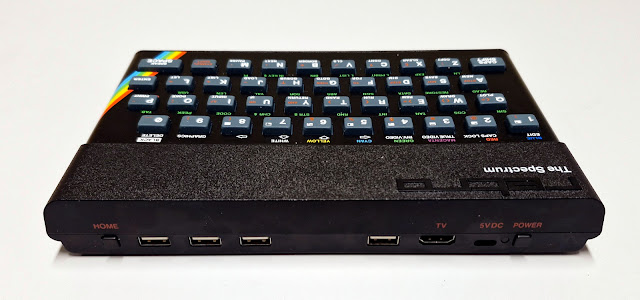 |
| The connectors and buttons at the back |
Retro Games have entered the USB-C age, which is good. I've powered The Spectrum happily with a 20000mAh power bank, using the 5V/3A output. A Raspberry Pi -type PSU should be optimal. I've not dared to use a laptop charger, though I'm not sure why it would be a problem.
The power cable is at the "wrong" side of the computer but it's sensible to have it near the HDMI, so as not to have wires dangling from both sides.
There's a power button so the cable doesn't need to be yanked away every time. There's one USB port near the HDMI and power cable, a good place for a semi-permanent memory stick holding your games and original system ROMs.
Then there are three additional USBs, perhaps for two controllers and one for ... keyboard, if you really want to.
And a home button at the right side, surely a familiar idea to users of Multiface cartridges of old. From here you can access the game selection carousel and other system menus.
The triad of USBs is nicely placed where the original Spectrum had the edge connector, contrast this with TheC64 which had nothing at the cartridge port location. I can imagine a 9-pin joystick adapter taking its rightful place here.
Keyboard
The most important thing for me is the keyboard. Because if it doesn't work, then I'm nearly better off using an emulator on the PC. So, does it pass the muster?
First I'll say it's better than the Elite Recreated keyboard from around 2015, which I tried hard to like in my review back then. For the record I have to admit it had the Sinclair logo, and the case was perhaps in some ways more accurate.
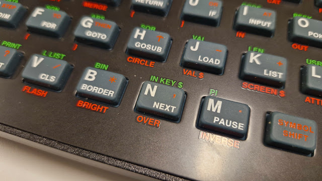 |
| They might not be exactly identical to the original Spectrum keys |
I couldn't shake the feeling The Spectrum keyboard is a little mushy too. But this was at least in part because I had no sound on while in BASIC. Perhaps an added psychological sense of "snappiness" comes from that sound.
Turning sound on did make it more comforting, although it would be nice if the sound came from the insides of the case itself. Maybe a DIY hack will surface.
Playing games, the key presses are usually silent so the above point shouldn't matter at all. How does the keyboard fare as an authentic Spectrum controller?
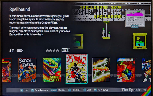 |
| The built-in games are chosen from a "carousel" |
I'll say I was fine with it. Using the holy QAOP combination for games worked well, I didn't experience missed key presses or physical obstructions. Epic games like Lords of Midnight and Elite are more enjoyable this way than with a PC keyboard. I can even use the original keyboard overlays.
Perhaps surprisingly, I couldn't get into adventure games with this keyboard. I tried a few, but soon turned away in frustration. It's not the keyboard as such but the wonky and slow input that Speccy adventure games often had on offer, and I'm not a big fan of the genre anyway.
Typing BASIC works well, and this is one major difference to PC emulators. There you have to feel your way around a non-standard keyboard layout to produce the BASIC keywords. No such problems here, but admittedly it takes some guts to use that old rubber for programming.
Then some nitpicks.
It's interesting to note the printing on and around the keys are positioned just a little bit off. Perhaps it could be even an IP matter, made just different enough so it's not a full facsimile of someone else's work?
But that's not all...
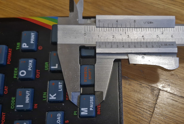 |
| Retro Games The Spectrum: ~9.6mm |
The keys are just a tiny bit smaller than in the original Spectrum. This was my first intuition, and when I took out the vernier caliper, I could see the original ZX Spectrum has almost exactly 10.0mm size keys, and The Spectrum has them in the 9.6-9.7mm territory.
I'm wondering if they shrunk unexpectedly in the manufacturing process.
To me this raises the question if the original rubber mat would fit the new machine. It did seem to me the holes in the metal plate are correctly sized.
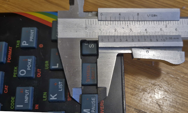 |
| Sinclair ZX Spectrum: 10.0mm |
Joystick
As my Arduino joystick 9-pin adapter didn't work with TheC64, I was a little sceptical (spectical?) if it would work on The Spectrum. But then news started coming in that nearly all USB game controllers work, and I was ready to be optimistic.
I must say it passed with flying colors. I can attach a TAC-2 controller and play games without having to resort to a modern gamepad.
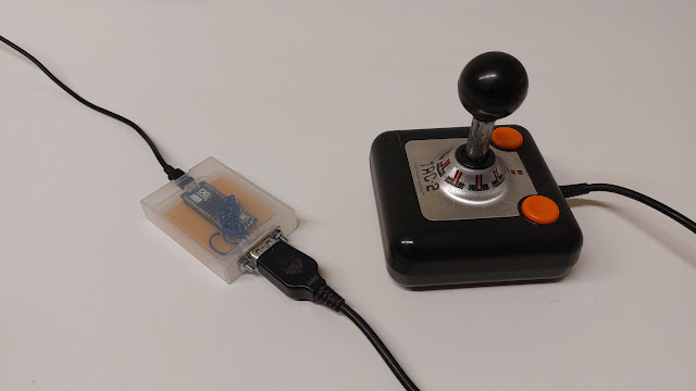 |
| This one here. |
Two controllers can be set, and there are ample options for configuring them.
I didn't even try the Retro Games Competition Pro-style USB joystick that came with TheC64, I assume it works and is just as bad as before.
I have no intention to test lag scientifically. My gut feel is that there is likely not much lag, but if you really go looking for it you might find it.
Spectrum games rarely have a very fast screen update anyway, so any lag would probably be lost within the general chunkiness. Using my Joystick adapter and 50hz HDMI display, I didn't feel anything was off in the fast paced Atic Atac.
Video
50hz and 60hz screen refresh rates are provided, and you have to make that choice when you first boot the computer.
I think it's crucial The Spectrum is connected to a 50hz-capable display, for authentic speed. Fortunately I have such a display, so no problem there. Normal TV-type displays can likely do this better than some computer monitors.
The screen is scaled in an integer-based way, so I didn't see any interference patterns or moire-type effects, not on a 2560 x 1440 resolution display or 1920 x 1200 display. Why I even bother to mention this is that I've found some non-commercial emulators difficult to set up in this respect.
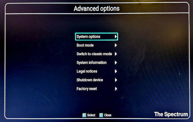 |
| The clear menus you'd expect from Retro Games |
For authenticity, the amount of BORDER displayed can be adjusted, and this is also a game-specific setting.
For my tastes, the non-bright color levels and the BRIGHT levels are a little too close to each other. My experience from the original is that the boot-up white screen is grayish, and the bright white really stands out.
The BASIC program below is a very rudimentary test that tells me The Spectrum generates a rock solid frame rate.
10 PAUSE 1
20 BORDER 0
30 PAUSE 1
40 BORDER 7
50 GO TO 10
Seeing "tear" or other hiccups would indicate a less than ideal experience. The border should flash consistently, as it does on The Spectrum.
A 50hz smooth frame rate in a Spectrum game is quite rare, so it's not surprising if games are not silky smooth. But it may be indicative of more subtle timing issues in the hardware? To be really sure, I would have to compare outputs to each other side by side.
After seeing a few demos that showcase horizontal scrolling, it was easier to see the frame rate is indeed smooth. It may be that a 50hz in a modern display is more mechanical than a CRT with some afterglow.
To get audio, I needed to use my HDMI-to-VGA with 3.5mm audio splitter, and it worked just as well here as with TheC64.
System
Games can be loaded using a USB stick. It should be FAT32 formatted, and you need to have games in folders that have a maximum of 256 files each.
I'd recommend NOT to have 1000s of games at hand, but to concentrate on a smaller number of games you know you can return to, and maybe a few unfamiliar ones you intend to have a crack at.
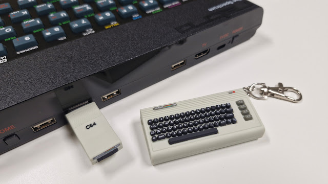 |
| A suitably themed memory stick... |
I don't have much to say about the 48 game collection that came with the computer, haven't yet tried them all really. To me it's a combination of hits and misses, some obvious inclusions (Manic Miner) and some obvious omissions (the Ultimate catalog).
From older games, I prefer simple and short ones such as Saboteur!, Bruce Lee, Splat, or Viking Raiders. But just sometimes, more epic is more fun, as with Lords of Midnight or Elite.
Compatibility issues may arise because the Retro Games ROM for Spectrum is not a Sinclair/Amstrad ROM. Fortunately this can be changed, if you think you have a permission to use the ROM. These need to be added to a specific folder path on the USB stick, THESPECTRUM/roms/ (See the large manual p. 48)
Using the default Retro Games Ltd system ROM, I could see that Manic Pietro, which uses a timing-based graphics engine to circumvent the normal attribute limits, showed some flickering. Switching over to Sinclair ROMs, this flickering ceased.
Here I have to say a speed boost would have been welcome for games such as Lords of Midnight, or Viking Raiders. But The Spectrum is set at the standard 3.5Mhz. There is a rewind option for cheating.
There are no timing adjustments, for example the "Pentagon" timings are not possible, and 128K appears to be the memory limit.
There are some reports of snapshots not working. I did find a snapshot of Bruce Lee, which works on Fuse emulator, but crashes reliably on The Spectrum. This with Sinclair ROM or not. These situations can be fixed by searching for an alternative snapshot or TAP file.
Final words
For someone who already knows their way around Spectrums, this may be just another collectible to fill the shelves. But I think it succeeds better in reaching its goal than TheC64 did, which wasn't bad either.
Some questions were left open, such as if it's possible to use an older Spectrum rubber mat, or modify an existing keyboard membrane to work on The Spectrum. Maybe I'll look into this eventually.


