Showing posts with label soldering. Show all posts

Wednesday, 16 November 2022

Korg Nu:Tekt NTS-1 ma:SSaKred

128mm wide, 78mm deep, 17mm high (excluding controls)

I got this about 100€ tiny brick of a synth, Korg NTS-1, or Nu:tekt. You build the case yourself and it has that rugged circuit board aesthetic. There's also promises of customization, both in hardware and software.

So, is this the Arduino of synths? Well, yes and no.

Yes, because it can be modified, and there are pins for accessing inputs and outputs. Yes, because it is very tiny. No, because the software architecture uses uploaded modules and it is not as "open" as an Arduino is. Yes, because you can also compile your own modules. No, because there's not a huge row of pins to access every meaningful aspect of the synth.

NTS-1 is not unique, there are several build-yourself-a-synth models around. The self-building aspect is at least partly a gimmick. But it's a nice product idea, potentially bringing the cost down a little. NTS-1 was really simple to put together with the instructions, no soldering or extra tools were needed. I used a somewhat larger screwdriver than the one supplied.

There are a few pins and soldering points that can be used to expand the synth. MIDI, audio and the sync clock are present both as ports and on-board connections. The real changes to the sounds and functionalities are done through uploading different modules.

I had somehow thought I could also use Nu:tekt as a MIDI-controlled adjustable filter, something you don't see that often. To my disappointment the audio-in is diverted to after the filter, and you can only select whether you want mod/delay/reverb affect your audio input.

But this is not the end. It is possible to upload new oscillators, modulators, delays and reverbs via the Librarian app. So I could add third party filters from DirtBoxSynth just to fix my grievance. This added some ~€10 to the cost of this device. Whether these filters are as good as the fixed ones, I can't vouch for.

The Librarian app

I also learned the architecture is shared between Korg Prologue and Minilogue, which means there's a wider market for these modules. Not all modules might be applicable for the context of NTS-1.

The Librarian app is only available for Mac and Windows, but fortunately it worked well in my 2012 Mac. A glance at the coding side makes me feel it wouldn't be impossible to compile my own effect (there are tutorials and examples) but it's doubtful I can do the math for anything useful.

Apparently an imported module only fits a particular category, so you cannot upload "bitcrusher" to Delays or Reverbs, it has to go to Mods. If so, I cannot choose to chain the DirtBoxSynth filters with the bitcrusher, it's either/or, because both go to Mods.

Ok, let's look at the more physical side of things.

The headphone is at the other side

The boards and the elements are meant for constructing the default box, so it's not a set of legos. Still, the process is nearly reversible and you are not stuck with the box you built. It should be easy to remove one of the four 1mm side panels, and replace them with your own, for example.

About that "nearly reversible". Because the instructions said so, I cut off the four screw holders from the board corners. As far as I see now they do not need to be removed when making the standard case. So, be aware when building the case you are making a permanent change! 

The controls are integrated to the top panel, which doesn't look too simple. The ribbon keyboard input connector looks a little tricky, attaching an alternative keyboard is probably not going through that route. Either find out what the pins between the top/bottom do, or use MIDI.

Header pins and four screws keep to cover in place.

The NTS-1 has no patch storage, but this is a minor inconvenience, considering all parameters can be transmitted via MIDI Control Change messages. There are Oscillator, Filter and Envelope types, with A and B parameters for each. On top of that you can have Mod, Delay, Reverb, LFO and Tremolo. There is also a rather full-featured Arpeggiator.

Like all the audio and sync ports, the MIDI port is 3,5mm one, with tip-ring-sleeve arrangement. So one of the first customization decisions might be whether you need an adapter cable (be aware of Type A and Type B) or build your own full-size MIDI port using the solder points inside. This is what I did, not long after putting the thing together.

The USB also connects the device to your computer as a visible MIDI device, so whether you even want to use the MIDI port for connecting is up to you.

Adding the full-size MIDI port

The box was even easier to open than to put together. The front or the rear panel needs to be removed before the circuit board can be lifted out.

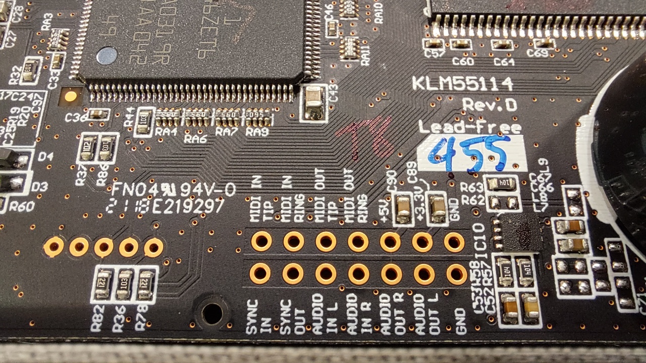
After removing the board it is easy to access the through-holes for MIDI, AUDIO and SYNC. Note that 5v and 3.3v can be drawn from here too.


I soldered in a header strip for testing. Then I realized the jumper cable heads would not fit under the cover, so I instead added a tiny layer of prototyping board. A ribbon connector might have been helpful here.

This way I can solder/de-solder wires should I need to change them. I wouldn't want to heat the actual Nu:Tekt board too many times.

The MIDI in "tip", "ring" and GND("Sleeve") need to be connected to a MIDI DIN-style connector.

I soldered the wires on the proto pads, as it was too tricky to nudge them from the underside after the board had been fit to place. There's one more layer of that header strip keeping the board higher.

I could have soldered the wires beforehand from the more correct direction, though.

Internally, MIDI channels are 0-15, in hex 0-F, whereas software and documentation refers to them as 1-16. This discrepancy sometimes rears its head and creates confusion, but I've become used to it.

How to change the MIDI channel? Consult the manual. Plug in the Korg and press REVERB at the same time, you get to the parameter menu. Find the parameter CHL with the Type knob and change them using the B knob. Push ARP to store the parameter to the internal memory.


Monday, 28 December 2020

Some more BMC64

Just a small update on putting the Raspberry Pi BMC64 Commodore emulator inside a Commodore 64C case, as described in the previous post.

The starting point:


I chose a suitably sized prototyping board with unconnected holes, sawed off the corners to make the Rpi screws fit. Then I soldered a 2-wide female pin header for the Raspberry GPIO and a 1-wide pin header for the C64 keyboard connector.

Then I soldered all the connections, trying to keep track of the mess. I lost the track once but fortunately it was not too difficult to re-solder a few wires. Soldering wires into pins isn't ideal, but tinning the wire ends prior to soldering helped a lot.

In hindsight I should have used a bit lighter, more bendy wire as now I had to push them down to make the C64C cover fit.

The end point (for now):

That horrible hole is the trapdoor for getting the SD card out. Sorry.

It's now quite compact.

I didn't do the joystick connections at the same time which was silly as they will be more difficult to solder now that the keyboard wires are in place.

Instead, I soldered a joystick connector in from the underside, aiming for the GPIO Bank 2 pins.

After a few mistaken solders, I found out I need to be careful which GPIO configuration I am aiming at, and also understand that I'm looking at the GPIOs from below the board. 

Now, it's getting crowded in here.

When using both the Keyboard and Joystick from GPIO, the pins are different than when using a joystick-only configuration.

So, in this case I used GPIO U=20, D=19, L=16, R=13, F=26 and Ground to get my joystick connected.

The joystick port is made from a PC COM-port as it had the correct sized header for the pins. Nothing has been properly fixed to the case but this shouldn't take too much work.


In use

If there's a Commodore 64 lying around, I sometimes write nonsensical little BASIC programs. Multiplication table tutors, tiny games, graphics effects, PETSCII scrollers, whatever.


This time my excuse was that I needed to test the keyboard more extensively.

And it works, I had really no trouble in getting to that BASIC programming mood with the BMC64 and the C64C keyboard.

A word of warning with the BMC64 emulator: Any changes to the attached D64 disk image will not be preserved if you don't detach the image first! So if you save your BASIC program to the attached D64, always remember to detach it before shutting down.

I also tried my go-to game for testing joystick lagginess, Buck Rogers (catridge image). Playing with a TAC-2 joystick I can feel a tiny amount of lag if I really concentrate on it. The BMC site says the joystick is only read alongside the screen sync, considering that it's not bad at all. Most games would probably poll joystick once a frame anyway, then depending on how it's done I guess the lag could vary.

Thursday, 30 November 2017

Sinclair QL EPROM


A 28C128 EPROM chip can be connected to the Sinclair QL through the 16K plug-in cartridge ROM port. The memory occupies the space (0xC000-0xFFFF).

I can't guarantee this is the 100% definite way to do it, as I haven't been able to compare this to an existing EPROM cartridge. But it worked for me.

The diagram below shows the basic connections between the QL ROM port pins and the EPROM, with a 7400 chip between.

The 7400 IC should be connected to the 5V and GND too. In addition, two capacitors should be connected to 5V / GND near the two ICs. I had 100nF, which I hope to be ok.

In the above diagram, the NAND gates represent the activity of a 7400 IC for combining the signal of A14, A15 and ROMOEH, connecting the final output to the pin that controls the EPROM enable state. (Low=enable) The data lines should only be active when all of the A14, A15 and ROMOEH signals are high.

I was unsure about the role between -G (gate control) and -E (standby), as the device works when connecting both together. According to the EPROM datasheet the -G is used to set output enable/disable whereas the -E can be held low for device selection.

"Data is available at the outputs after the falling edge of G, assuming that E has been low [...]" makes me think that it's not a big deal timing-wise but it might be clearer if E was low all the time.

I have three QLs, and my first cartridge attempt worked in one of them. This led me to waste time thinking the "fault" could have been something about the differences in the QL models. In this version I had left the A14 and A15 floating, assuming the ROMOEH signal is enough to indicate the 16K area is addressed.

However as it should have been quite obvious from the start, the signals of A14 and A15 need to be combined with the ROMOEH, as the ROMOEH signal is high whenever the whole ROM area (0x0000-0xFFFF) is being read, not just the 16K area.


I used a Toolkit II ROM as a guinea pig. The onboard ROM (version JS) seems to find it "twice" which I hope is normal. The TK2 functions can be activated with the TK2_EXT command and all seemed to be ok.

An EPROM cart like this isn't especially useful these days, as many modern expansions do not work at the same time. Full 64K on-board ROM? Can't use the port. QL-SD? Can't use the port. Tetroid Disk Interface? Can't use the port. So, I'm left with a QL that can have a 16K EPROM and pretty much nothing else.

However this might be the beginnings for making something else, a transfer device etc.

Edit 14.12.2017: I burned 2.20 version of the Toolkit II, which has the FSERVE fileserver. The file server works nicely from the ROM module and is a quite powerful function to have. It alone justifies this little project, maybe I'll write about it later.

The parts list:

-27C128 EPROM + 28 pin socket
-7400 NAND chip, such as SN74LS00, + optional 14 pin socket
-2 x capacitor, I used 100nF

(Ignore the top image which has all kinds of unnecessary things added to it.)


The board

I have been hunting for a good PCB prototype board that would suit the project. It should be obviously with 2.54mm raster and double-sided so that it may have something that works as an edge connector.

I ordered a set from eBay with different sizes. The 50 x 70mm board with 18 x 24 raster is simply a perfect fit for the QL ROM cartridge slot, and there are 16  pads at the edges that just about work for the connector after modifying the board a bit.

The sixth position is cut off, to a depth that includes only the first through-hole. The QL case slot is wide enough for the 50mm width so nothing else needs to be cut.

The prototyping board and the blade for removing through-plating.
The raster holes are plated through, and as the pads are very short, this means the holes would immediately short the top and bottom connector pins. I suppose a variant without through-plating might exist, but it is difficult to tell from the eBay listings.

I rotated a paper/exacto knife blade from both sides of the hole, this way I could get rid of the through-plating from the row nearest to the pads. After all it is a very thin layering. This needs to be done briskly enough so that the chipping away can be felt, yet carefully enough so that the holes don't get ruined.

In the first row I need to be certain there is no contact between the two sides, no dust or thin filaments. This phase adds a bit of tedious handiwork.

The cut could be deeper but then the next row of through-plating should be removed too. One row is just enough for holding the cart in place. The pad width acted as a good guide for the cut width in this prototyping board.

What follows after is likewise tedious connecting of the pads to the chips by wire, for both sides. There shouldn't be too much solder on the pads, so I tinned the wires beforehand and tried to carefully connect them to the pad edges. Even then I made a bit of a mess, and I cut away extra solder with the paper knife.

There's a method for creating paths by solder for this type of board, but it's also slow and results in huge lumps of solder. I used wires for connecting nearly everything.