Thursday, 20 November 2014

BASIC Interpreter


I have been doodling a BASIC interpreter, written in Processing. A BASIC interpreter is something I've always wanted to do, with varying levels of ambition, resulting in various abandoned attempts.  "Abandoned" meaning they couldn't be said to work as BASIC. Now, the current project is beginning to resemble a working language.
The multiplication table in "hi-res". Note that the FOR...NEXT structure is still absent. Also, the parser currently requires some superfluous brackets.
Instead of trying to create a modern IDE + compiled BASIC (which there are plenty), I wanted to make a sort of virtual computer inspired by 1980s machines, with limited fixed-memory space and limited character "display modes".

I'm also trying to project how BASIC-based computers might have developed if history had followed another course. This shouldn't be taken too seriously, though. What's here is a mash-up of cherry-picked features benefitting from hindsight. For example, even if I've kept the graphical capacity of the "computer" pretty low, the storage space is near-infinite. This was not at all the situation in the end of the 1980s.

Although I admire various BASIC interpreters from the 1980s, the most significant source of inspiration comes from Sinclair QL SuperBASIC environment. I like the idea that a computer would be used not so much for running "apps", but giving enough building blocks for making interesting things. Arguably Linux/UNIX environments do this already, but woefully they inherit a bit too much from the text-terminal days. Instead, the BASIC interpreters were directly coupled to visuals and sound. Currently the emphasis is on a character display-style interaction with the visuals, but other "display modes" could be inserted just as well.
The obligatory "scroll some random garbage on screen" program.
The virtual machine contains 128K of "RAM", which is partially mapped as character display, character set graphics, free memory and system parameters, BASIC listing, variables and stack, just like the 8-bit computers.  I'd say this arrangement was even helpful at times, as it creates a straightforward division between "in-computer" variables and the Processing variables: the entire memory and all the virtual computer parameters are simply inside a byte array in Processing.

Although a Sinclair-style separation of graphics and command entry has merits, I went for full-screen cursor editing. (With some as yet half-baked windowing features.) The BASIC listing is line-numbered, something I chose for simplicity but also for certain immediacy. If it's not meant to be an IDE, let's not even go halfway there. Supporting some labels might still be viable, and I hope to have Sinclair QL-style procedures unless they prove to be too difficult.
A fragment from a BASIC program for editing the character set. It's a bit slow.
I kept the amount of memory low (128 kilobytes) because I wanted instant saving and restoring snapshots of the entire machine state, and for this reason the images should not take too much space on the disk. Saving the entire memory is much like saving a snapshot in an emulator, everything will be conveniently contained in it, colours, character display, character set, cursor position, BASIC listing, system variables, just everything.

One difference to emulators is that the snapshots can be loaded with commands during run-time. A major reason for this is to enable hypertext elements for traversing between snapshot images. So it's not necessary to "program" anything to make use of the screen editor. The old BASIC systems worked as on-screen scratchpads, and here, before the BASIC was functional, I could use the screen editor as a notepad for future features and to-do lists and general thinking-out-loud.

The system variable reference, as a memory snapshot. The [bracketed] text typed on-screen act as commands, which may invoke other memory snapshots.
However, I did not go so far as to emulate a processor, in which the BASIC would run. This would have been cool but far too difficult and time consuming for me at this moment. I have to raise a hat to anyone who made these things work in the 1980s and before. Here the Processing code is used to parse the BASIC commands, arranging all the memory reads and writes and handles the updating of the display.

What's the most difficult part here? The "pipeline" of functions that identify the keywords and elements in a BASIC statement and return values to various expressions and functions.

This kind of line could be entered in the full-screen character display:

CLS: PRINT "Hello world: ";PEEK(32128+PEEK(64));" times"

After the program scoops the ASCII string from the full-screen editor, it is sent to the pre-parser, which decides whether it ought to be added to the BASIC listing (not, because there is no line number) or run immediately.
A one-time scheme of the command pipeline, as a memory snapshot.
When run, the pre-parser splits the line into the two separate command lines, CLS and PRINT, divided by colons (:), yet ignoring the colon inside the quotation marks. So far quite simple. Then the command lines are sent one by one to the proper parser, which splits the statement into components. The components are separated by either space, comma, brackets and so on. (This is a bit more complex than I'm letting on).

With PRINT, the parser needs to handle an arbitrary amount of expressions, which can be strings or numeric variables or functions, usually separated with a comma. All of these are sent one by one to the Resolver, which identifies other parts as strings and others as something to be sent to the Calculator/Counter. The Counter is a recursive function which breaks the PEEK(32128+PEEK(64)) part, first the PEEK(64), re-working the initial string into PEEK(32128+1) (for example) and then into PEEK(32129), which is finally seen as a straightforward function, returning the contents of the address 32129, which might be 255. This is turned into a string and put on screen.

This is all a bit messy, and my hands-on style of improvisational programming means that a change in one part easily means an unexpected result in some other part. It's all been going on fairly well, though.
Possibly a support for cyrillic alphabet...
Is it available? No, at least not yet. Probably never, if past projects are any indication. There's too much work to be done ensuring the program works nicely and does not provide a potential backdoor for destroying somebody's files. If I do my own programs for myself there is a massive amount of work I do not need to care about. (better error-handling, some user-friendliness, manuals, support) There's a message here somewhere, I think.

Why? It's an interesting thing to do. Also it might help in devising scripting languages and word parsing for something unrelated.

Tuesday, 21 October 2014

Canon X-710 Plotter


I've always sort of wanted to own a plotter, but never went for full pro equipment. Guess I knew I'd just want to play with one. Plotters at home never caught on that much, as the other printing techniques were eventually able to produce similar results on the A4-size. Still, there's something elegant about that paper-traversing pen.

Well, here's one tiny toilet paper holder plotter for Canon X-07. It came together with yet one more Canon X-07 computer. One of the neat ideas was that grey binder that covers the machine. Now, here the very same design has been simply extended to cover both the computer and the plotter, and it looks simply ridiculous. For comparison, Canon X-07 and a Canon X-07+plotter side by side:

It will probably fetch $1000 from eBay at 2025.
Incidentally, don't think the X-07 is worth more than 40-50$, please.
The plotter is simply packed together with the computer, and it has to be connected to the X-07 with an external parallel cable. The connector is an 8-line wide bus, activated with a strobe signal. The plotter prints straightforwardly any text you throw at it, except in the drawing mode text commands are used to move the pen around.

PSU-modded. I suppose the mechanism is identical between CBM, Sharp etc. models.
First, I had to do the power supply mod to make the plotter work without the battery. Canon apparently aimed to create a fully portable system so the power supply included is really a "battery charger".

The pens that came with the plotter had dried a long time ago, and attempts at rejuvenating them with water have failed despite coughing up some ink. So, I ordered some plotter pens from eBay. These are old too, but supposedly never opened. (They cost more than the plotter. Some things never change). They are not perfect, but still, I'm surprised they work at all.

Cleverly, the pens are contained in the paper roll axle. (centimetre grid)
The graphic mode has to be activated with LPRINT CHR$(18). Subsequently, commands such as LPRINT "M0,0" will move the pen to coordinates 0,0 with the pen up. LPRINT "D100,100" will bring the pen to coordinates 100,100 with the pen down, drawing a line in the process. Pressing Reset on the plotter will reset the pen and takes the plotter back to the text mode. The new 0,0 coordinate will be at the new pen position.

At the moment, it seems my plotter has some difficulties changing the pen colour reliably. It may be because I somehow wrecked the delicate parts of the pen revolver when replacing the pens. Oh well.

Note that here the black pen had some trouble when moving right.
The bottom left corner is "bolder" from multiple passes.

From what little I have seen this tiny plotter is able to keep the coordinates very well. The printer uses a mechanism to perforate the paper slightly from the edges. These tiny holes are at the same time used for holding the paper in position (much like matrix printers use the ready-made holes to align the paper).

It appears that most of these small plotters of the era used the same ALPS mechanism with pens of same size, so Sharp, VIC, Casio and Canon plotters might have interchangeable parts.

But who was the intended user for the plotter, or for that matter, the strange Canon X-07+plotter combo? Imagine in 1983, a businessman pulling it out of the bag during a meeting, throwing together some lines of BASIC that plot out the latest sales curve projection...

It's a big world out there, son, and you've got to compete. No time chasing balls of string.
With the Canon pltoter, you can have that crucial edge...

Wednesday, 15 October 2014

Binary silliness

Ok, something a bit weird for a change.

Many old books on computers start by teaching the principles of binary notation, and conversions between hexadecimal and decimal. This is usually shown with something resembling the 128*b7+64*b6+32*b5+16*b4+8*b3+4*b2+2*b1+b0 formula.

From An Introduction to Microcomputers, Volume 0: The Beginner's Book. Third edition. (Osborne & Bunnell, 1982)

Yet if I ever worked with hex, I would never really grasp this mathematical underpinning of the system. If I wrote a snippet of C64 machine code, to me "$D020" would be the memorized "name" of where I put the border colour value, and I would not really give much thought to what it was in decimal. Similarly, I just knew that $C000 was 49152, without doing the conversion.

Also, when building user defined graphic characters on the Spectrum BASIC, I'd be lazy and use the BIN 00011000 style statements instead of converting them into the shorter decimal form. Even then, if the patterns were simple and repeated often, I'd use 255 for BIN 11111111 and 24 for BIN 00011000 because I "knew" these values by heart, not because I was good at calculating the decimal in my "head".

Yes, visually simple but a bit silly.
Yeah, I can nowadays get along between small binary, decimal and hex values, but I could still do better. Although the modern programmer does not need to know that much about binary or hex, with retro computers and digital electronics, they are quite relevant.

From my previous experiences, I have begun to think, why would learning binary be different from learning guitar chords or another alphabet? People can memorize numerous guitar chords without having a through-and-through understanding of the mathematics of the chord theory. Did the computer books go a bit wrong way about the whole binary thing, especially for beginners?

I think the guitar chords are a good example: Through perseverance, a number of chords can be memorized directly. Knowing three chords, something satisfying can already be played. Then you can add more chords to your repertoire as you learn more complex and more satisfying songs. But learning hits really when you see that somewhat similar chords can be grouped sensibly.

The Binary alphabet

With this in mind, I began pursuing a learning approach that would help me convert binary/hex/decimal. I can't vouch for any "system" here but perhaps this gives some ideas.

The "Binary Alphabet"

I imagined each hex number to have an alternative 4-bit binary "glyph" or notation that needs to be memorized. These are simply binary versions of the same numbers, yet visualized as blocks. I've abandoned the 0/1 notation, because we're not necessarily dealing with numbers, but HIGH/LOW,  ON/OFF and TRUE/FALSE states, or indeed, bitmaps.

Most of us carry practice equipment with us. Just don't go showing a "4" around in public places.

With eight-bit numbers (0-255 or 0x00-0xFF or $00-$FF) the amount of "letters" in the alphabet would be too big to memorize. However, only 16 "glyphs" are really needed when moving between hex and binary, because each hex number corresponds directly to four binary numbers.

Each 8-bit hecadecimal number is made out of two such components. Below is an example of a few of such combinations. Referring to the above alphabet, it can be easily seen how the hex values are built, without any "calculation" going on.


This would already form the basis for the notation of 8x8 characters, familiar from 1980s micro computers. Note that as the required pieces are repeated, there's a need for only a few distinct values. (Remember the three-chord analogy...)


A lot of 8x8 graphics can be worked out with just $0,$3,$6,$9 and $F.

Alphabet groupings

Normal letters are grouped to wovels and consonants, musical chords can be sharp, flat, diminished and so on. Grouping can advance learning and analysis. Both the alphabet and chords are often teached from the simpler towards the more complex. Below, I have attempted to group the binary glyphs according to simplicity and order.

Looking at the table below, it should be Obvious, that 0x0 is 0000 and 0xF is 1111. Also, the basic components, 1, 2, 4 and 8 ought to be Simple to learn by heart.

But it should be apparent, that by moving the block right or left, the number becomes divided or multiplied by two. This holds true for all binary graphics that can be moved so that the figure still stays intact. This is really the basis of the grouping here. So, 0101 is five (0x5) in decimal, but 1010 is ten (0xA). The point here is that knowing one can lead to knowing the other, knowing 5 you will know 10 and vice versa.


There's only three "letters" that are not grouped in this way in the above system, 0x9, 0xB and 0xD, as the can't be shifted. (Neither can 0 or 15, but they are exempt from this difficulty anyway.)

There's another way to group the binary family that might be helpful. The image below limits the family to eight "root" glyphs, which is half the number of 16.


Each of these base values are +1, if the last bit is set. Each 4-bit binary value that has the last bit 0, can be changed into a value+1 by setting the bit. This may seem a bit strange at this point, but consider the ungrouped values above. The 9 can be considered an "8" with +1 added, the "11" is "really" a "10" with 1 added, and "13" is a 12+1.

I only show this because it has some resemblance to the way guitar and piano chords can be varied by adjusting the last note. (Think the difference between the open guitar chord C and C7) This is more to demonstrate that there are a number of approaches by which to exercise your binary muscles without going too deep to the math side of things.

Another additional tool is to learn to rapidly invert the values and gain the result from a simple calculation. Meaning, each of the empty/white regions are considered black and vice versa. Looking at 1001, I can think of 0110 which is 6. at which point I have to think "15-6" which brings up 9, the decimal value of 1001. But this is already a bit cumbersome and introduces calculation in a way I hoped to avoid.

I think the sixteen shapes could simply be learned by heart. Most of the above might be dismissed as tricks that can be somewhat helpful in the process of learning. Yet they also have the added significance in that inverting and shifting are also common and useful operations in machine code and discrete logic. To "know" binary and hex is to "know" how they are to be manipulated, it is not simply a matter of converting them between each other.

Towards larger numbers?

The conversion between binary and hex should be fairly simple, even if the numbers are larger. So, 0xC020 is 1100 0000 0010 0000, and 0xB4CD becomes 1011 0100 1100 1101.

At this point it should be good to be able to instantly recognize the hexadecimal and the decimal value of any 4-bit binary number, and the decimal values 0-15.

Indeed, what about decimal conversion? Here I'm on a bit shakier ground. For 8-bit numbers (0-255), one could learn a second "alphabet", for the higher part of the byte:


These are the previous values * 16. This value will have to be added with the lower part, and I'm uncertain if this is more handy system than simply adding all the binaries individually together just as the books say.

Besides, the route for converting decimal values back to binary is not as obvious. You would have to see that a value such as decimal 119 is above 112 yet below 128, and so would have the 0111 high portion.

The shifting rule of course always works, so 224 (1110 0000) shifted right is 112 (0111 0000) and vice versa.

For 16-bit numbers, I'm afraid there would have to be one more of these alphabets. A 16-bit number is High byte * 256 + Low byte, but here are only the highest 4-bits of a 16-bit value:


This may seem unreasonable to memorize, and the shifting rule becomes less useful. But if I'm targeting an understanding of a typical 8-bit computer memory map, it becomes somewhat more meaningful. The memory can be visualized as 16 equal-sized (4k) chunks. Available memory spaces and memory mapped portions in 8-bit computers often start from such "even addresses", for example the VIC chip of the C64 starts at 0xD000, 0x1101 0000 0000 0000, 53248. The ZX Spectrum screen memory address (and RAM altogether) starts at 0x4000 = 0x0100 0000 0000 0000 = 16384. 0x8000 is the halfway point in 16-bit memory space, 32768.

So, a 0xC000, 49152, is 0x1100 0000 0000 0000, and 53280 (The C64 border address) is 1101 0000 0010 0000, 0xD020.

Yet, the above is less helpful for deciphering a random 16-bit value. I'd need yet another "alphabet" for the lower part of the high byte, which I just can't think is the road to go now.

Just an example. Not worth the trouble really.
So, the system would end up being exactly the kind of addition-game I was hoping to avoid in the first place. The best bet might be to use a combination of memorization and the "book system" of counting the 32768+16384+8192+4096+2048+1024+512+256 values together.

But, umm, yes, anyways. At least the hex-bin thingy is easy. And 8-bit numbers are not that bad. I think I'll go back doing whatever I was doing.

Tuesday, 2 September 2014

FlashAir, A wireless SD-card

Toshiba FlashAir is an SD card with built-in wireless network capability, so it's possible to transfer files from/to it with the card sitting inside another device. As many retro-computers now have card readers, it might be interesting to have wireless transfer to a card. Let's see...


Marq took the plunge and got the cards, and he has been working toward a script that allows more flexible card use. I was at first sceptical, as the product seemed like something that would only work inside a (specific) camera or something. And, yeah, that seems to have been the original intent, sort of. Only, clever people have found out there are undocumented features in the card that allow uploading to the card. For the retro-enthusiasts among us, this should be the more interesting part.

Well, if most people only want a huge collection of snapshots/tape images on a card, a wireless card might not be that interesting. But for a 8-bit cross-developer, the wireless card offers an interesting route toward running code "instantly" on the real target hardware, if that computer has an SD card reader, that is. But I'd imagine it would also add convenience for general file transfer.


Following the instructions here, I could get the card to work eventually. Now that the work has been done by others, it is quite simple. Still, I misunderstood a couple of points so I'll follow with hopefully even simpler instructions.

A word of warning, though. There's relatively little experience about these things and the card might simply fail eventually. It's an undocumented feature, after all.

Steps:

1. There is a configuration text file CONFIG on the FlashAir SD card folder SD_WLAN. Back it up and modify it with a plain text editor. Normally the card operates on APPMODE 4, which is for downloading (image) files from the card. Crucially, this is changed to 5, upload is enabled, the card is given the ID and password to your WLAN.

Following the instructions here, the config file, when modified, looks something like this:

[Vendor]

CIPATH=/DCIM/100__TSB/FA000001.JPG
UPLOAD=1
APPMODE=5
APPAUTOTIME=0
APPNAME=AirFrame
APPSSID=Your wlan SSID
APPNETWORKKEY=Your wlan password
COMMAND=wlan 11n 1
VERSION=[hidden]
CID=[hidden]
PRODUCT=FlashAir
VENDOR=TOSHIBA
MASTERCODE=[hidden]
LOCK=1

(I've hidden everything that might even remotely be tied to the identity of my own card. Obviously your config will have these lines already filled in.)

2. Now, the card should be ready to be inserted into a computer SD-card reader. For clarity I would suggest using some other computer/device than your mac/pc/linux. Not that there should be problems.

Wait for a while for the card to boot up. (About 15 seconds)

3. As the card is powered up, you'll need to find the IP address of the card. On OSX, a PING 255.255.255.255 from the Terminal ought to reveal the card, if it is working at all in the APPMODE 5. If there's a lot of addresses you have to figure out which one is the card. You might start pinging before you insert the card, and after about 15 seconds it should appear in the list.

4. Then open your browser, go to address http://n.n.n.n/upload.cgi (where n.n.n.n is obviously your card address just revealed). You will be greeted with a minimal file-selector and a "submit" icon, which is used for sending your files to the SD card.


Check Marq's work on the script I linked above for more sophisticated card use.

*

Some of my experiences with the FlashAir card and different computer/card reader combos:

ZXEvolution:

ZXEvolution has an SD-card reader built-in, it is pretty much the main storage device there. On the Evo the card seems to work perfectly: I can send files at any time, and resetting the Evo does not reset the card.

5/5

Sinclair QL + QL-SD card reader:

QL-SD is a bit problematic, because of the QL_BDI.BIN drive image scheme. Even if the card worked smoothly, rewriting the entire QL_BDI.BIN is not that useful. (I have not tried the QL-SD in the "native" mode, as the user manual advices against it.)

Also, the SD card can become fragmented easily and after that the QL may refuse to mount it. So you have to format the entire card and make sure that QL_BDI.BIN is the first thing you copy there. However after this is ensured there should be no trouble.

It also seemed that the presence of the card on the WLAN was a bit erratic.

2/5

Commodore 64 + SD2IEC card floppy:

The server does not seem to run while the card is inside the SD2IEC. I can't hazard a guess as to why it is so. At least without alterations SD2IEC with FlashAir is a no go. This is a bit sad as the FlashAir could have made the SD2IEC into something so much more.

0/5

HxC SD Floppy Emulator:

A very generic SD card reader that works in Amiga, Atari ST, PC, Amstrad CPC and MSX etc... The server responds when a file is unselected, which is quite the expected behaviour. The file can be then uploaded, and chosen immediately afterwards. Perfect!

I've only tried it with Atari ST but the functionality should not depend on the computer platform in any way, so there's a lot of devices this could be connected.

5/5

Chromebook C720 ChromeOS/Linux:

The card works, but needs to be unmounted/mounted in succession before the uploaded files become visible for the file system. This is not too big a hassle but has to be arranged. On the ChromeOS side it is not clear how this could be done. Also, a modern computer is not an especially useful application for the card.

3/5

*

I've previously thought the FlashAir has been a bit of a hit and miss, but having HxC compatibility adds a massive amount of potential systems.

I've not tried all devices, though. There's still SD2SIO, Compact Flash/SD converters and so on.

Thursday, 14 August 2014

Rewriting Spectrum ROMs on a ZXEvolution/TS-Conf

Here I am exploring another interesting feature of the ZX Evolution, the Z80-based hobby computer that has ZX Spectrum modes. What I'm looking at here is changing the ROMs, as the Evo has a fully re-writable EPROM chip.

For a noble cause.
Using the ROM burner in Wild Commander file explorer, I can rewrite the ROM with some of the original Psion/Sinclair 16k ROM cartridge binaries. This is quite an interesting prospect for an old Spectrum-head, since these ROMs have been quite hard to get and usually require an Interface 2. Also, ROM burning usually requires some special equipment and boards, but the TS-Conf/Wild Commander makes it very simple.
I'm talking about one of these thingies. Interface 2 required, but not pictured.
There are a few 16k games for the Spectrum on the cartridge format. Since Ultimate/Rare has actively discouraged the distribution of their games, Jet Pac, PSSST, Tranz Am and Cookie binaries can be harder to find. This leaves Psion Chess, Backgammon, Hungry Horace, Horace and the Spiders, Planetoids and Space Raiders. The chess and backgammon games are pretty well done for what they are, Horace and the Spiders is nice enough and Space Raiders is a passable Space Invaders rip-off. Planetoids I don't care much about. (Of course, all these games are available on tape.)
ZX Spectrum 48k simplified memory map.

Burning chROMe 

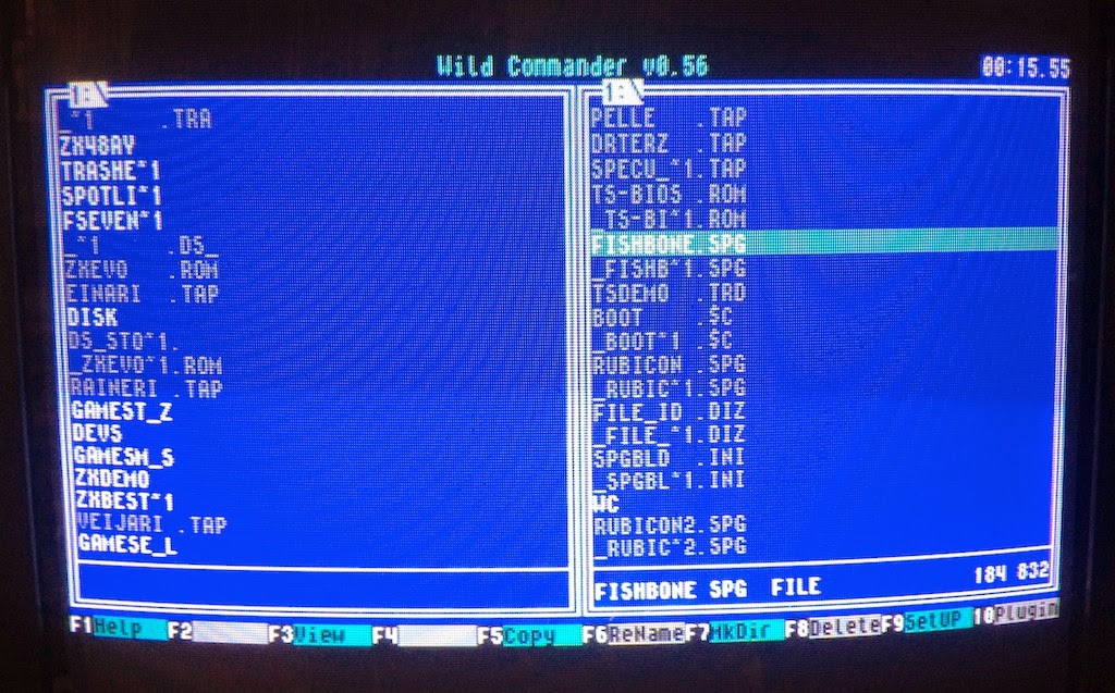
I've explained a little bit about using the TS-Conf and Wild Commander here. The Wild Commander is renamed as boot.$c and placed at the card root. Also, a WC folder at the root contains all the plug-ins and the INI file that lists them. Selecting a .ROM file activates the ROM WRITER plug-in, if it is correctly installed.

The version number 0.1 tells that we are doing this on our own responsibility...
After picking the ROM file select the block #01. DO NOT use the ROM block #00. I did once, and although the computer nicely boots to the desired ROM, it will not boot into anything else after that! (Thankfully I could flash the T&S firmware and rewrite everything).


Symbol Shift+F12 returns to the TS Conf frontend. Here, adjust the "Reset to:" into ROM #04 and use the bank SYS. After that, a plain RESET (F12) will activate the ROM.

ZX Evolution transformed into a chess computer.

Rom Writer v0.2 

Edit 2015: The new version of the ROM WRITER makes it possible to write the ROM files into RAM. When the ROM WRITER v0.2 activates, select the last option, RAM #F8.

Then, In the TS-BIOS Setup-utility use parameters Reset To: RAM #F8 and bank:SYS, then reset to run the ROM. Soft reset will not destroy the contents. This is very handy for testing ROMs.


Other ROMs

This here page describes efforts to build new ROM cartridges for the Spectrum, plus also the games mentioned above and some prototypes. There are also zx80, zx81 and the Forth-based Jupiter Ace emulators, which all run on the Sinclair Spectrum as ROM cartridges. The 128k versions can be burned on the ZXEvo and they work. They are not 100% compatible with the original computers but it is neat work nevertheless.

"Jupiter Ace" on a ZX Evolution. Ok, so I'm not very good at Forth.
Another exciting use for the ROM burner is re-writing or modifying the original Spectrum ROM. For example, there is some free space before the character graphic definitions. (14446-15615) Some code can be positioned there without harming compatibility. There could be utilities, a small machine code monitor, et c. (In the russian ROMs, the TR-DOS might get conflicted, though.)


Monday, 21 July 2014

TS-Conf for (us) Dummies


I've previously talked about ZX Evolution, the new "Spectrum" from Russia. What I did not mention there's something called the "TS-Conf", which makes more use of the underlying hardware. Don't ask me what it is, I don't fully understand myself. All I know it's not really a Spectrum anymore. It's maybe more comparable to the Amiga or some 1990s games consoles. Recently more demos and software have started to arrive on it. I've wanted to try it for a while, but very simple instructions seemed to be missing.

Now I at last found the time to make the configuration run. I used the soft reset key method of flashing the firmwares. This is just one way to install the TS-Conf, I think.


First:

Currently, the required files are perhaps best accessed from this forum post at TSlabs.

-Download the WildCommanderWide.$C file from the link that says about Wildcommander.
-Download the TS-CONF firmware zxevo_fw.bin from the first link that says "keyboard layout by NedoPC"
-Download the full 512kb ROM image zxevo.rom from the link that says "Full 512kB ROM image compatible with both TS and Base configs". This contains the TS BIOS. (Also as a separate file)

You need another firmware for flashing the zxevo.rom file. Following from this forum post, somewhat downwards, download the file from the link that says zxevo_fw.bin. The firmwares have the same name, so best have them in separate folders (first and second) or something... 

Edit: As pointed out in the comments, the Test&Service firmware has an English language option. After booting, press CAPS LOCK to activate. I only updated a couple of the images. Anyone who wants to use these computers should figure out a little bit of Russian :)


Step by Step:

-Copy the zxevo.rom and the second zxevo_fw.bin to the SD root. (Remember to backup the existing files.)

-Flash the firmware: Turn on Evo while holding down the soft reset key. A LED should start flashing, you can release the key.

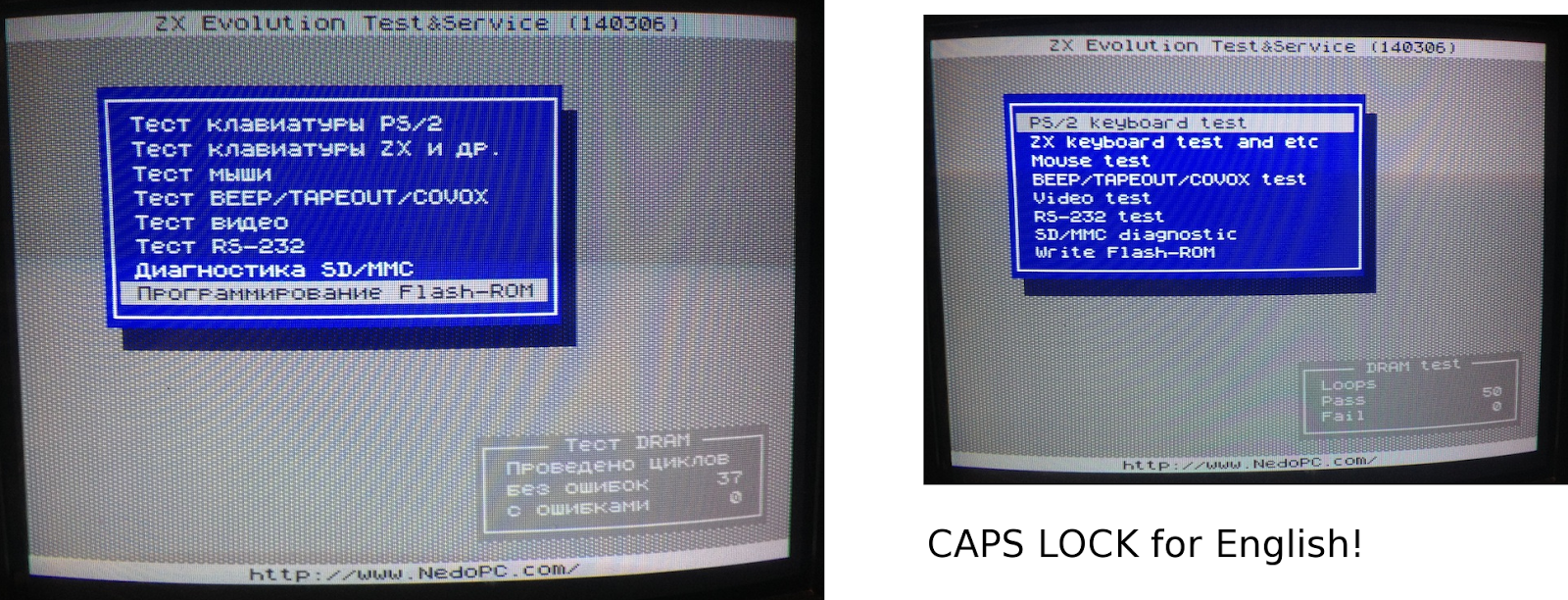
You should have something like this: (Left, in Russian. Right, in English)


-Go to the last item on the menu and select it. (That says something about a Flash-ROM)


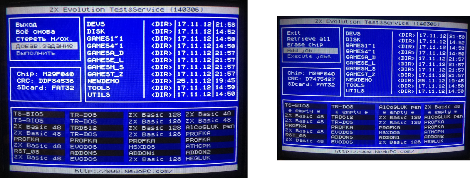
-Here, go to the second last item on the menu and select it.


-Find the zxevo.rom file and select it. 


-All the ROM slots will be yellow. Select.


-Go to the last item on the menu and select it.


-Press Y and wait...


-Everything OK. You can exit this menu from the top item.


-Now it's time to completely turn off the Evo. 

-Copy the first zxevo_fw.bin to the SD card root. This is the actual TS-CONF firmware. Again, overwrite the previous zxevo_fw.bin.

-You should have the WildCommanderWide.$C. Rename it to boot.$c, and copy it on the SD root.

-Flash the firmware: Turn on Evo while holding down the soft reset key. A LED is should start flashing, you can release the key. You should see something like this:


(Remember, pressing Symbol Shift+RESET should always return to this screen.)

-Change the "Reset to:" into BD boot.$c. Press RESET. (There's an alternate RESET that uses Caps Shift+RESET, that's why there is also a  "CS Reset to:")

The Evo boots the boot.$c file. If all is well, you should be in the Wild Commander screen. If there is no boot file or it is incorrectly named, you will have a black/red "system meditation" screen.


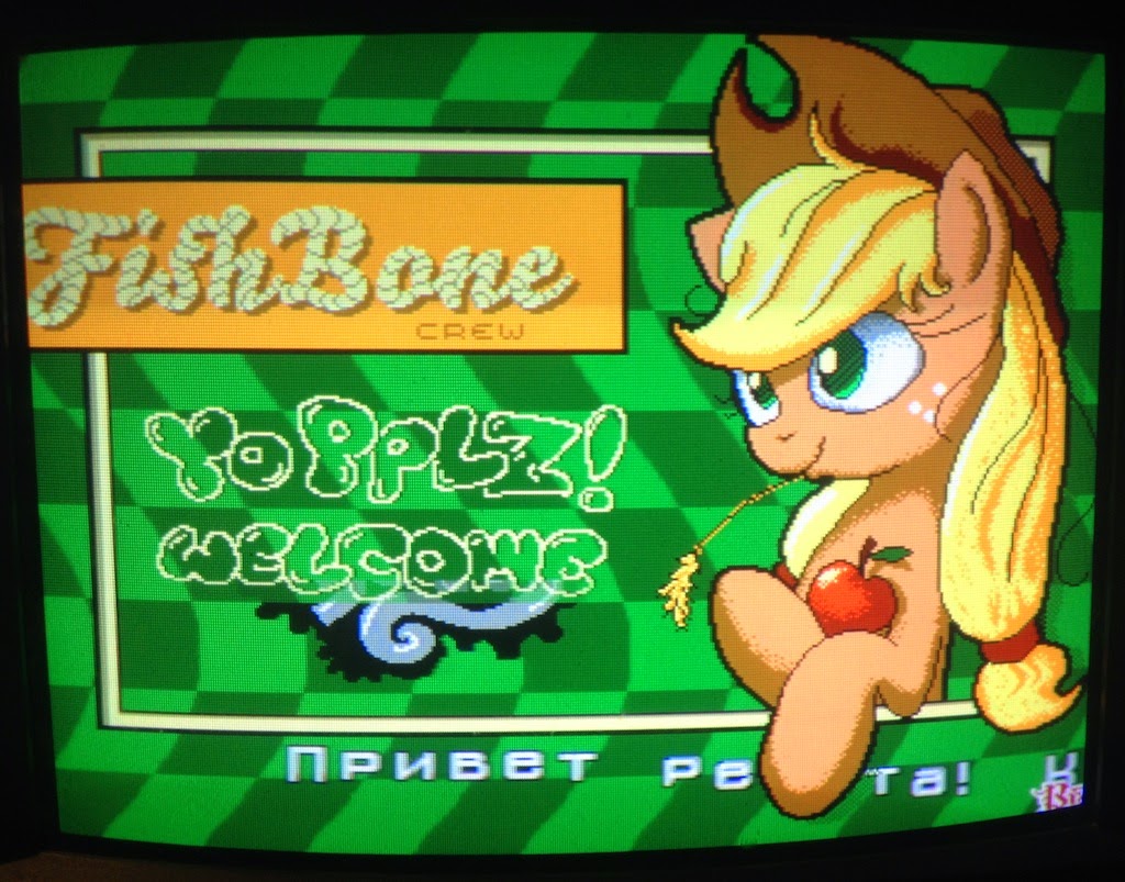
-Select a *.SPG file. I used this one for testing, you should of course copy it on the SD beforehand, or whatever you want to load. (It seems here you cannot load TRD images. Edit: Except if you install the required plug-ins. Check that link...)


That's it!


Wednesday, 16 July 2014

Loading JR200 files from Arduino


As a follow-up to Panasonic JR200 tape wave generation some years back, I now had an opportunity to use my specifications for a quick project. Here I have an Arduino UNO work as a "tape" storage for the Panasonic JR200. As the Panasonic JR200 really likes square waves for input, the Arduino digital pins are ideal for the job.

The Arduino produces the waveform over and over from a series of bytes. Using the MLOAD command from the Panasonic end, the computer will load the data next time it loops around. (Resetting the Arduino obviously restarts the "tape")

I spent some time figuring out how to power the Arduino from the Panasonic External Bus, which would be convenient. The first bottom left pin is the Ground. Checking with the multimeter, then, going right, there are five pins between the Ground pin and what appears to be a 5V pin.

Again, I have to say I like the JR200 more and more for the quality of the hardware. I cannot guarantee the below schematic is good for the health of your Panasonic/Arduino/self, but here goes anyway:

Not to scale. The JR200 connectors are as seen at the back of the computer.
I used this setup to load some converted ZX Spectrum loading screens. I noticed the loading can be made somewhat faster, as there's some tolerance in the tape input. At first I used 200 and 400 microsecond square wave lengths to simulate the original speed, but I soon found out that I can use 160 and 320 instead.

So, it might take 26 seconds to practically load a loading screen (4K in two files), that would normally take slightly over 30 seconds. Well, it's a small improvement anyway. At 150ms/300ms, the Panasonic stopped recognizing the signal.


If only I could get rid of the trouble of writing the MLOAD keyword. However, I can at least load BASIC keywords directly into the character display, for example A=USR($1000). So, booting JR200 and using MLOAD would result in a more complex command set, waiting "under the cursor". Machine code can be run from the character display, so a tight package could combine both the necessary keywords to run the code and the code itself.

In glorious flicker-o-vision:


Further ideas:

-Take some signal from the Panasonic to Arduino for triggering the loading. Perhaps the "remote" relay. As the Panasonic gives an audible click when using the MLOAD, there's got to be a relay somewhere.

-The Arduino could just load a short code for high-speed receiving from the joystick port(s).

-Saving files to Arduino. It should be simple enough, but I just can't see the point.


The Arduino sketch:

Copy/Paste to the Arduino editor and upload. Use MLOAD from Panasonic. The example loads just 8 bytes to the character memory. This gives a quick visible effect. For sending your own data, change the contents of the g_data array list. The g_length and g_address are used for setting the start address and the length of the data. The g_offset sets the starting point from which the data is sent, within the g_data array. This only matters if you want to send multiple files.


#include <avr/pgmspace.h>

#define OUTPIN 9
#define MSHORT 200 //160
#define MLONG 400 //320
#define MLONGEST 800 //640

// Panaduino
// Uses Arduino pins to send a tape signal to Panasonic JR-200
// 15.7.2014 Dr. TerrorZ

unsigned int g_level,g_chek,g_blok,g_length,g_address,g_offset;

// The data.
// PROGMEM is necessary for anything longer.
// The actual g_length, g_address and g_offset are set in loop()
// 

prog_uchar g_data[] PROGMEM={1,2,4,8,16,32,64,128};

void switchlevel()
{
  if(g_level==LOW){g_level=HIGH;return;}
  g_level=LOW;
}

void send0_600()
{
  digitalWrite(OUTPIN,LOW);
  delayMicroseconds(MSHORT);
  digitalWrite(OUTPIN,HIGH);
  delayMicroseconds(MSHORT); 
  digitalWrite(OUTPIN,LOW);
  delayMicroseconds(MSHORT);
  digitalWrite(OUTPIN,HIGH);
  delayMicroseconds(MSHORT); 
  digitalWrite(OUTPIN,LOW);
  delayMicroseconds(MSHORT);
  digitalWrite(OUTPIN,HIGH);
  delayMicroseconds(MSHORT);
  digitalWrite(OUTPIN,LOW);
  delayMicroseconds(MSHORT);
  digitalWrite(OUTPIN,HIGH);
  delayMicroseconds(MSHORT);
  g_level=HIGH;
}

void send1_600()
{
  digitalWrite(OUTPIN,LOW);
  delayMicroseconds(MLONG);
  digitalWrite(OUTPIN,HIGH);
  delayMicroseconds(MLONG);
  digitalWrite(OUTPIN,LOW);
  delayMicroseconds(MLONG);
  digitalWrite(OUTPIN,HIGH);
  delayMicroseconds(MLONG);
  g_level=HIGH;  
}

void send0()
{
  digitalWrite(OUTPIN,g_level);
  delayMicroseconds(MSHORT);
  switchlevel();
  digitalWrite(OUTPIN,g_level);
  delayMicroseconds(MSHORT);
  switchlevel();
}

void send1()
{
  digitalWrite(OUTPIN,g_level);
  delayMicroseconds(MLONG);
  switchlevel();  
}

void sendlong1()
{
  digitalWrite(OUTPIN,g_level);
  delayMicroseconds(MLONGEST);
  switchlevel();  
}


void filler600(int a)
{
  int i;
  for(i=1;i<=a;i++){
    send1_600();
  }
}

void filler(int a)
{
  int i;
  for(i=1;i<=a;i++){
    send1();
  }
}

void sendbyte(int a)
{
  int b,c;
  send1();
  send1();
  send1();
  send0();
  b=1;c=a&b;
  if(c!=0){send1();}else{send0();}
  b=2;c=a&b;
  if(c!=0){send1();}else{send0();}
  b=4;c=a&b;
  if(c!=0){send1();}else{send0();}
  b=8;c=a&b;
  if(c!=0){send1();}else{send0();}
  b=16;c=a&b;
  if(c!=0){send1();}else{send0();}
  b=32;c=a&b;
  if(c!=0){send1();}else{send0();}
  b=64;c=a&b;
  if(c!=0){send1();}else{send0();}
  b=128;c=a&b;
  if(c!=0){send1();}else{send0();}  
  g_chek=g_chek+a;
  if(g_chek>255){g_chek=g_chek-256;}
}

void sendbyte600(int a)
{
  int b,c;
  send1_600();
  send1_600();
  send1_600();
  send0_600();
  b=1;c=a&b;
  if(c!=0){send1_600();}else{send0_600();}
  b=2;c=a&b;
  if(c!=0){send1_600();}else{send0_600();}
  b=4;c=a&b;
  if(c!=0){send1_600();}else{send0_600();}
  b=8;c=a&b;
  if(c!=0){send1_600();}else{send0_600();}
  b=16;c=a&b;
  if(c!=0){send1_600();}else{send0_600();}
  b=32;c=a&b;
  if(c!=0){send1_600();}else{send0_600();}
  b=64;c=a&b;
  if(c!=0){send1_600();}else{send0_600();}
  b=128;c=a&b;
  if(c!=0){send1_600();}else{send0_600();}  
  g_chek=g_chek+a;
  if(g_chek>255){g_chek=g_chek-256;}
}


void header(int id)
{  

  //in 600 baud format

  g_chek=0;
  sendbyte600(2);
  sendbyte600(42);
  sendbyte600(0);//block#0
  sendbyte600(26);//fixed length of data for block #0
  sendbyte600(255);
  sendbyte600(255);
  sendbyte600('P');//filename 16
  sendbyte600('D');
  sendbyte600(48+id);
  sendbyte600(0);
  sendbyte600(0);
  sendbyte600(0);
  sendbyte600(0);
  sendbyte600(0);
  sendbyte600(0);
  sendbyte600(0);
  sendbyte600(0);
  sendbyte600(0);
  sendbyte600(0);
  sendbyte600(0);
  sendbyte600(0);
  sendbyte600(0);
  sendbyte600(1);//binary1,basic 0
  sendbyte600(0);//baud rate for the rest. 0=2400, 1=600
  sendbyte600(255);
  sendbyte600(255);
  sendbyte600(255);
  sendbyte600(255);
  sendbyte600(255);
  sendbyte600(255);
  sendbyte600(255);
  sendbyte600(255);  
  sendbyte600(g_chek);//checksum
}

void datablock(int len)
{
  unsigned int i,adhi,adlo,lbytes;
  unsigned int bb;
  unsigned char cc;
  lbytes=len;
  if(len==0){lbytes=256;}
  g_chek=0;//reset checksum
  adhi=g_address/256;
  adlo=g_address-(adhi*256);
  sendbyte(2);
  sendbyte(42);
  sendbyte(g_blok);//block nro
  sendbyte(len);//length 0=256
  sendbyte(adhi);//hi addy
  sendbyte(adlo);//lo addy
  for(i=0;i<=lbytes-1;i++){
    bb=0;
    cc=pgm_read_byte_near(g_data+(g_blok-1)*256+i+g_offset);;
    bb=int(cc);
    sendbyte(bb);
  }
  g_address=g_address+lbytes;
  sendbyte(g_chek); 
}

void lead_out()
{
  int adhi,adlo;
  adhi=g_address/256;
  adlo=g_address-(adhi*256);
  sendbyte(2);
  sendbyte(42);
  sendbyte(255);
  sendbyte(255);
  sendbyte(adhi);//hi addy
  sendbyte(adlo);//lo addy
}

void send_tape(int tapeno)
{
  int i,dblocks;
  int lef;
  
  dblocks=g_length/256;
  
  g_level=LOW;
  g_chek=0;  
  g_blok=1;
  
  //600 baud portion
  filler600(850);
  header(tapeno);
  filler600(51);
  
  //2400 baud portion
  for(i=0;i<=dblocks;i++){
   if(i==dblocks){
     lef=g_length-dblocks*256;
       if(lef==0){datablock(1);}
       if(lef>0){datablock(g_length-dblocks*256);}
     }
   if(i<dblocks){datablock(0);filler(196);}
   g_blok++;
  }
  
  sendlong1();
  filler(188);
  lead_out();
  sendbyte(255);
  filler(150); 
}

void setup()
{
  pinMode(OUTPIN,OUTPUT);
  digitalWrite(9,LOW);
  pinMode(13,OUTPUT);
  digitalWrite(13,LOW);
}

void loop()
{ 
  g_length=8;
  g_address=0xd000;
  g_offset=0x0000;
  send_tape(1);
  
  pinMode(OUTPIN,OUTPUT);
  digitalWrite(9,LOW);
  delay(100);
  
  //for multiple MLOADs, use separate tape loads.
  //delay(1500);
  //g_length=0x0800;
  //g_address=0xc100;
  //g_offset=0x0800;
  //send_tape(2);
}