(The text below was written entirely as a Sinclair QL SuperBASIC program, as an experiment to see how this computer from 1984 could be used for writing, without using a dedicated word processor application. At the same time, the text goes to describe the approach I took. I have not edited out or removed any typos or repetition, as they can indicate challenges in the approach. The mechanical paragraph division is also quite telling. The images and captions have been added in the Blogger.)
One of these, in case you forgot.
Introduction
I have previously suggested that the Sinclair QL is unique among the earlier home micros in that it might not need apps for rudimentary tasks. I made crude experiments with 3D 'modelling' and extrapolated that it might be a viable approach were the QL more powerful.
I did think however that this was mostly because the old BASIC-enabled micros were good as a graphic notepad, but for many other tasks the approach would not do. Now I'm beginning to feel that at least for writing, the QL superbasic might offer some ways in to writing.
It struck me that the QL might be easily used for producing text, without resorting to a word processing package. Obviously, there might be limits to the length of text that could be reasonably produced, but then again my modelling experiments were not professional quality either.
Such a project might go two ways. I could try to write a small text editor that would store the written text into memeory. Or I coold write the text as a program. I went for the latter, as it seemed to me more in the 'Spirit of QL', needs less programming talent, and frankly, might be the more powerful approach.
The Approach
The root idea is simplistic. One might take any old BASIC-equipped computer and type text into REM lines. I could then say this was what I was looking for: a way to produce text without an editor. Yet, with the QL, I was looking for something a bit more flexible.
I've taken the notion that the paragraph is the defining unit of text, and built a program around it. A paragraph, when thought out well, carries through a single idea from its' presentation to a closure, preparing for the next. I defined a PARAGRAPH proccedure which simply takes a text string as an input. The procedure then prints the text, tabbed and separated with a line from other paragraphs.
Preparing to edit The Approach subheading, consisting of three paragraphs.
A paragraph is a suitably short unit of text to be handled in the slow SuperBASIC console. Even then, the few sentences need to be written quite unhesitatingly into a finished condition, because editing the middle and the beginning of the paragraph easily becomes too slow.
Structuring the text
The text body could be a list of PARAGRAPH lines, but it is also useful to have some control over the entirety of the text. For this purpose, I made each text subheading into a named procedure, such as INTRO, APPROACH and STRUCTURE.
The procedure definitions at the heart of the program. The variable CHindicates the desired channel. CH=1 would send the text to screen.
Each of these procedures are made from a heading line and a few paragraphs. The HEADING is another procedure, which simply prints the intended heading name and a separating line. So, when the program is RUN, the text will flow from top to bottom, separated with the appropriate subheadings.
However, the best use for these structuring procedures is that from the console they display a particular portion of text. It is better than using the LIST command in conjunction with line numbers. Now, INTRO can be used to view the introduction, APPROACH the middle part and so on and on.
Listing the The Approach subheading using APPROACH procedure.
I tended to keep each section below such a length that it would about fit the Sinclair QL screen in 80 column mode. This way, a portion could be seen at a glance. This of course limits the kind of texts that are meaningful to produce in this manner. CTRL+F5 can be used for pausing the overlong text, though.
Experiences during writing
I noticed there was still a need to contain each heading into a simple to grasp system of line numbers, so I could use a LIST command to explore the section under writing. I put each of the headings 100 lines apart, so a simple LIST 100 TO 200 would give the introduction, for example.
Although the paragraph and heading system could be used for shifting chunks of text into different order, I still found it most effective to write the text mostly in the order it was needed. I had very little need to change the location of written text. It was more likely I could write 'in between' existing text using a new PARAGRAPH line.
I have shown the way text can be easily produced and viewed, but there is still the need to store the text into a proper ASCII file. For this purpose, some more programming is needed. (But not much.) The procedures that use a PRINT command text, ought to print to a channel. This way, the channel can be a file or a serial output.
Concluding remarks
I hope the above works as a kind of a proof-of-concept for showing that the QL could be used for text editing purposes even without a dedicated app. The SuperBASIC lends enough power to structure the text beyond the most immediate editing capabilities.
The part of the listing that describes the entire text structure. RUN would then list the whole text.
Again, this experience can be extrapolated, asking the question, what if QL was much more powerful and flexible? This kind of approach to text creation might be more interesting and challenging that the kind of WYSIWYG processors we nowadays have.
Admittedly, the writing process was somewhat more cumbersome than even a simple current text editor might afford. But command lines also give something that the more direct approaches do not. Invoking the different portions through commands gave a sense of control and somewhat exotic feel to the writing process.
Another caveat here is that the writing genre here supports the approach I've used. If I needed to more heavily edit the existing text, or mold new ideas, I might find this way a bit too slow. Also, fiction might be a bit cumbersome to write.
Then again, the QL gives an added bonus of absolute focus to the task, which is nowadays easily lost among the clutter of internet browsers, multiple windows and social media. I'm only left with the QL keyboard, nothing else to do but to produce the text. If I need to pre-plan the text, I do it on paper or inside my head. No messing about with stream-of-though within a text editor.
I'm looking forward to experimenting further with the Sinclair QL SuperBASIC to explore what kind of productive areas it might be applied to.
Here are some of my very first experiences with QL-SD card reader for Sinclair QL, the Most Interesting Computer in the World. This is a recent solution, designed by Peter Graf and manufactured by Paul Veltjens. It allows to bypass the dreadful Microdrive and gives a larger capacity drive image for loading and saving files.
The device is very straightforward and it's also really simple to install. Although it is a kind of a prototype, the device appears quite well thought out and clean. No soldering or messing with the QL: You only need to open the QL and replace a couple of chips.
Lazy man's install. The card reader is intended to replace one of the Microdrives.
The manual is extremely well written and helpful, but I'll summarize the process anyway.
Backup the files that already exist on the SD to your PC/Mac/Linux. From the included folder, unpack a suitable sized drive image (Such as QL_128K_BDI.BIN if you have unexpanded QL) and rename it to QL_BDI.BIN. Copy it on the card top directory, overwriting the previous file. Put the card back in the reader.
Open the QL case (leave in the two screws below the microdrives, and oh, be careful with your keyboard membranes).
Remove the two ROM chips from the QL and insert the QL-SD ROM chip. I found the chip somewhat tight to insert. The pins are a bit short, so make sure the chip is firmly in place.
It's possible to replace the physical microdrive with the reader so that the card sticks out neatly from the existing drive opening. The circuit board has ready-made holes for this.
What you should see after a succesful installation.
Then, off you go. Turning on the QL brings up the Minerva logo, and you have a possibility to bypass the reader. Minerva is one of those improved ROM thingies, which holds overall enhancements over the original QL ROMs. The default setup also boots to the Toolkit II extension, which longtime QL users swear is "absolutely
necessary". The TK2 helps with directory structures, networking, multitasking
and offers a plethora of handy new commands. But if you need to make the boot slightly faster and save some memory, the Toolkit can be made optional.
A bit sad thing here is that the unexpanded QL can only really handle 3MB drive images. This can't be helped. But let's not despair, that's still more than 35 microdrive cartridges! (And from what I get modern memory expansion options are soon arriving.) But anyway, it all depends what you want to do with your QL. For now, I'm quite happy to mess around with the SuperBASIC and fiddling with the boot file.
Toolkit II loaded, listing multitasking jobs
As I have two QLs, I'm interested in the possibilities for using the second QL as a "pure" vanilla machine, connected to the QL-SD boosted computer. So far, I had no luck in using the Toolkit II FSERVE command for setting up a file server, which would have been cool. I did load and run the Toolkit via LBYTES to the second QL, though. The network loading seems to quit altogether after I activate the Toolkit II. This may be due to memory, Toolkit II or it's just something I don't yet understand about the syntax. It's probably nothing to do with the QL-SD per se as the network works fine without the TK2.
The QL-SD appears a very good solution for SD card reading, something I've been waiting to happen for QL for some time. I can only hope these will be available in the future too.
Bluetooth keyboards are notoriously expensive. I thought this cheapo bluetooth keyboard from "iZound", aimed at the iPad mini, might be bearable. And it could have been. It's just that, who thought it would be a good idea to shift the QWERTY-row one step to the left? Also, as much as I appreciate the scandinavian keys, I'd still think a comma would be more useful as a direct key... And, it appears that the backspace is really a delete key. Uh.
It is a truth universally acknowledged, that as the ZX Spectrum does not have hardware sprites, the programmer is left to concoct her own bitmap graphics routines. It's
something every aspiring Spectrum coder should try to do! Recently me and Marq have been exploring fast and smooth sprite graphics on the 48k Speccy. It's a much discussed topic, yet remains fascinating. Moving graphics can be done in so many ways, and it is not always obvious what to aim for. Games use various tricks to ease the load, and the tricks in turn depend much on what the game is about.
It's still wise to try to build a generally useful sprite engine, before optimizing for different contexts. So far we have managed eight 16x16 masked, freely positioned, flicker-free, smoothly moving sprites, as shown in the above video. (Check also this Youtube video)
This first part opens up the basics of the topic. If I get to write an improved version, there will be a Part II.
A 16 x 16 sprite is a common starting point. Any problems related to it can be applied to larger sprites. The above image shows a 32-byte definition of such a sprite. From left to right, top to bottom, the bits would translate to following decimal bytes:
This corresponds to the way the Spectrum stores pixels, one bit per pixel, a byte for eight pixels. The memory-mapped screen is found from the address 16384 onwards. A POKE 16384,255 in BASIC will quickly show this.
Screen BASICs
The ZX Spectrum display is notoriously a bit disordered, so one of the first issues is to resolve the drawing order. At first glance, it would seem to be enough to increment the drawing address with one byte for each column and 256 bytes for each row. Then, a routine like the one below would render our sprite on screen:
5 REM DOES NOT WORK
10 LET ADD=17184
20 FOR B=0 TO 15
30 READ L
40 READ R
50 POKE ADD,L
60 POKE ADD+1,R
70 LET ADD=ADD+256
80 NEXT B
100 DATA 7,224,24,24,32,4,78,2
110 DATA 95,2,159,1,142,1,128,1
120 DATA 128,1,128,1,128,25,64,58
100 DATA 64,50,32,4,24,24,7,224
If only:
Uh oh.
But we're on right track somehow. At least something is happening on screen. As it stands, the address logic changes after every eighth pixel row, as shown in the diagram below. The picture shows in detail the structure of the top left corner of the Spectrum screen, where I tried to draw my sprite. Inside the character row, each pixel row is nicely 256 bytes apart, but the first addresses of each character row are 32 bytes apart.
Furthermore, the screen is divided into three 64-pixel high "slices", each having a start address 2048 bytes apart. Zooming out, the leftmost screen addresses for each character row (every eighth pixel row) are laid out as follows:
This ordering is quite good for drawing 8x8 characters aligned to the character rows. One might even call the Spectrum screen layout a pseudo-character display. But a generic sprite routine has to negotiate the 8-line "boundaries" as well as the two "slice" boundaries.
The BASIC program below identifies the slice block and character rows for a given vertical pixel coordinate, and draws the "sprite" accordingly.
10 FOR S=0 TO 15
20 LET Y=11+S
30 LET BLOCK=INT (Y/64)
40 LET CROW=INT (Y/8)
50 LET YR=Y-(CROW*8)
60 LET CROW=CROW-(BLOCK*8)
70 LET ADD=16384+BLOCK*2048+CROW*32+YR*256
80 READ L: READ R
90 POKE ADD,L: POKE ADD+1,R
100 NEXT S
110 DATA 7,224,24,24,32,4,78,2
120 DATA 95,2,159,1,142,1,128,1
130 DATA 128,1,128,1,128,25,64,58
140 DATA 64,50,32,4,24,24,7,224
OK, indeed
The object described here hardly deserves the name "sprite". BASIC is simply too slow, and there's lot more to do than just laying the bits on screen. Proper sprite routines can only really be done in machine code.
Even then, it's possible to improve the above listing, by calculating the addresses beforehand into a table. It would be a bit silly to calculate the address for each sprite row.
10 REM PREPARE A TABLE
20 DIM A(176)
30 FOR Y=0 TO 175
40 LET BLOCK=INT (Y/64)
50 LET CROW=INT (Y/8)
60 LET YR=Y-(CROW*8)
70 LET CROW=CROW-(BLOCK*8)
80 LET ADD=16384+BLOCK*2048+CROW*32+YR*256
90 LET A(Y+1)=ADD
100 NEXT Y
110 REM DRAW THE SPRITE
120 RESTORE 180
130 FOR I=0 TO 15
140 READ L:READ R
150 POKE A(11+N),L: POKE A(11+N)+1,R
160 NEXT I
170 DATA 7,224,24,24,32,4,78,2
180 DATA 95,2,159,1,142,1,128,1
190 DATA 128,1,128,1,128,25,64,58
200 DATA 64,50,32,4,24,24,7,224
At least in this respect, writing sprite routines in assembler is not that different. It's about finding ways to offload the burden from the drawing parts. This is why many fast routines use a buffered drawing of some sort.
Sprite shifting
The BASIC listings simplified many things. Much has been said about the vertical coordinates. How about the horizontal? Fiddling with the BASIC listings above would show that adding one to the sprite position address moves the sprite one character column to the right. This at least is straightforward, but it is not smooth. There are ways to recalculate the sprite graphics on the fly, but pre-shifted sprites are easier and faster.
A 16x16 sprite GFX and its' mask, with room for shifting.
Shifted 16x16 sprites are in reality 24x16 sprites, and each graphic needs 8 shifted variants. This way they can be aligned horizontally with the character columns. The downside is that it takes more memory.
All the sprite variants also need a mask, which is an inversion of the area that will be cleared before drawing the proper sprite. This way the sprites can be drawn over a background without showing any of the pixel background through the sprite, or producing other ill effects. Many games get away without using masks or backgrounds, and can even look better for it (think Dan Dare), but such an approach is hardly generic.
The machine code routines discussed below use shifted sprites.
Sprites in z80 machine code
Smooth sprite movement has to be tied to the screen update cycle, which is refreshed 50/60 times a second. In machine code, the HALT instruction tells the processor to wait until the refreshing beam has returned to the top of the screen.
After this, the beam travels right, returns to the left side of the screen and travels down, refreshing the screen during the process. To avoid flickering and glitches, changes to the screen should be done before the beam hits the drawing area.
So, a conventional sprite-drawing program might follow this order:
The z80 running at 3.5mhz can do quite a bit before the beam is arrives at the pixel area. (Or "the display file" as it is called in the official Spectrum manuals.)
Of course, even when the beam is in the pixel area, things can be drawn below the current beam position, and the results will still be smooth. Many scene demo effects take advantage of "racing the beam" in this way. Even a sprite routine may benefit from such a scheme, but for a generic routine the drawing is safest to do before the beam arrives at the pixel area.
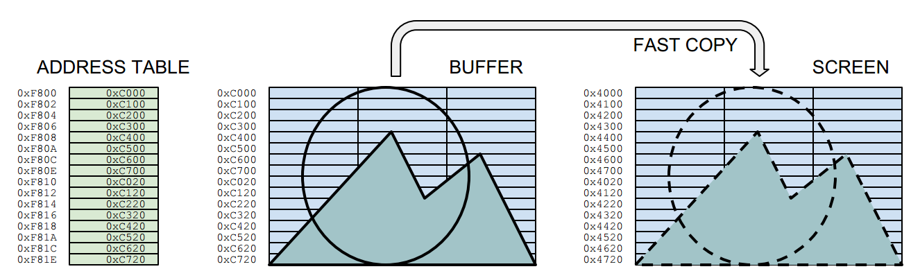
The sprite program shown in the video follows the order below. The border colours are not just for fun, but for showing what actions are being taken at that scanline position. The routine draws the sprites into a hidden buffer screen, and uses a fast copy routine to do bring them on the visible screen. An address table holds the position information for the fast copy routine.
BEFORE THE LOOP:
Copy the entire background image to the entire buffer
Draw sprites to buffer and create a new address table for them
LOOP PHASES:
Wait Vertical Blank (=HALT instruction)
RED: Copy bytes to screen from buffer, using the sprite address table
BLUE: Copy background to sprite positions at the buffer, using the sprite address table
YELLOW:Change sprite coordinates
BLUE: Store the address table
YELLOW:Draw sprites to buffer and create a new address table for them
BLACK: Wait until the beam is outside the pixel area (estimated)
RED: Copy background to sprite positions on the screen, using the stored address table
The sprites are drawn when the beam is on its "way in" to the pixel area, and wiped out on the way out. It is a bit unelegant to have to wait at the end, as the waiting time depends on the computer speed. So, this solution is fixed for the original 48k Spectrum timing.
Note that here the sprites are drawn well before the beam arrives at the pixel area. The fast copy routine could even move 12 sprites to the screen. Yet drawing more than 8 sprites altogether (buffer, clearing) is not yet possible. It's easy to see though, that there are ways to reduce the load, especially the needless duplicating of the address table.
Buffered drawing
In this sprite routine, there are three "screens": The real display screen, a source background image and the drawing buffer. In addition, the sprite graphics need to be stored somewhere.
The diagram below shows the Phase 6 in the above list. (The second "yellow" portion.) Here we draw the sprite to the invisible buffer screen and store its screen position as an address into the sprite address table for later copying.
The actions required for drawing a single byte are highlighted. The diagram only shows the part relevant for the sprite, which in this case is drawn to the top left corner of the buffer, waiting to be moved on the same relative screen position. The mask and graphics are interleaved for purposes which is explained later.
Phase 6: The diagram illustrates how the sprite is drawn into the buffer screen.
Each time the sprites are drawn to the buffer, an address table is also renewed. The address table is at the heart of the fast drawing routine (phase 2). One sprite has 16 rows, so drawing a sprite to the buffer also writes 16 addresses to the table. The address table points to the locations in the drawing buffer, from which the sprites are copied after the HALT:
Phase 2. Fast copy from the buffer to the screen
This means a lot of the calculations needed for computing the outcome (such as the row boundary calculations and combining the mask/background) are done in hiding, whereas the fast copy is only concerned with moving bytes directly between the buffers and screen areas.
In z80 assembler, the fast copy might look something like this:
buffercopy:
ld sp,#addresstable
pop hl ; row 1
ld d,h
ld e,l
res 7,d
ldi
ldi
ldi
pop hl ; row 2
ld d,h
ld e,l
res 7,d
ldi
ldi
ldi
pop hl ; row 3
ld d,h
ld e,l
res 7,d
ldi
ldi
ldi
...
...
...
[16 rows for each sprite]
addresstable:
; Just an example, a sprite in the top left corner
The stack pointer is placed at the beginning of the table, and the addresses are loaded in the HL register using POP HL, which also increments the stack pointer by two. The LDI performs the equivalent of LD (DE),(HL), moving the contents from address at HL to the address at DL, incrementing both DE and HL in the process. For 24-pixel wide sprites, three LDIs are required for one row.
The table could have from-to address pairs, but writing both addresses during buffer drawing proved to be a bit cumbersome. So the "destination" address DE is constructed out of the "from" address HL by altering the high byte. This is a tiny bit slower than POP:ing both from the table, but it also keeps the table shorter for copying purposes. (phase 5)
This address shifting also means the buffer locations cannot be freely chosen. 0XC000 (49152) and the screen address 0X4000 (16384) are in a good relation to each other, as only one bit needs to be changed between them. There are three versions of the above routine, all different depending whether it is about BUFFER->SCREEN, BACKGROUND->BUFFER or BACKGROUND->SCREEN copying.
The lines
Let's get back to where we started: The ZX Spectrum screen order. Despite the fast copying routines, the sprites need to be drawn into the buffer, and at least somewhere during the process, the line order needs to be negotiated. It's no good if the buffer drawing routines, even if hidden, are too slow.
The overall assembler source is a bit too daunting to publish here, as it is largely a Processing-generated bundle of tables and repetitive code, held together with some C. So I'll stick to explaining the overall idea and some of the more interesting points.
Obviously there has to be a table that contains the drawing address for each vertical pixel row. But accessing this table 16 times each time a sprite is drawn would be less than optimal. This can be avoided. But if one wants to avoid conditional jumps (and one wants to avoid them) there has to be a number of variants of the routine, depending on which pixel row the sprite is drawn to.
With eight sprites, any commands added to the pixel drawing order gets repeated not only 8 times, but 128 times or more! So there's a great incentive to remove slow code from the heart of the buffer drawing.
It would be neat to just have a full sprite drawing routine for each vertical pixel row. This would produce 175x16 copies of the sprite row drawing code, which takes far too much memory. The amount can be reduced: there are only 23 ways how a 16-pixel high sprite drawing might unfold. This would produce "only" 23x16 times the row drawing code. It doesn't sound much but still it's more than 20 kilobytes, a bit too much.
What we did was a bit nasty: self modifying code. One pixel row drawing code is repeated only 39 times. Each variant has it's own labeled entry point. When the sprite drawing is invoked, the program jumps into the relevant entry point, depending on the sprite vertical coordinate. (Yet another table) The diagram below describes the whole code portion and an example case:
The example sprite is to be drawn at Y coordinate 20. A vertical address table tells that this row uses the variant 4. The NOP (0x00) instruction at the address of EXIT4: label is overwritten with a RET (0xC9) instruction. HL is loaded with the label ENTRY4: address. JMP (HL) takes the program counter there.
The routine then draws four rows, skips the character boundary, draws another eight rows, skips another character boundary, draws four more rows and exits the drawing routine. The RET is overwritten with a NOP.
There have to be rewritten exit points, because only 16 rows are needed, and we want to avoid conditional jumps and wasting registers on counters. So, drawing sprite variant 0 means jumping to the entry label 0, while writing a RET to the EXIT0:. Jumping to entry 4 means writing a RET to the exit point 4 and so on.
The code below describes what happens within the "draw row" portion in the above diagram.
; stack is pointed to the beginning of sprite graphics
; (mask and gfx interleaved)
; de holds the drawing address
; jp(hl) brings the program counter here
; bc holds the beginning of the address table
ENTRY0:
; de is written to the address table
ld a,e
ld (bc),a
inc bc
ld a,d
ld (bc),a
inc bc
; draw one sprite row to the buffer (3 bytes wide)
; stack handily gives both the mask and the graphic byte
ld a,(de) ;get buffer byte
pop hl ;get mask and gfx
and a,l
or a,h
ld (de),a ;draw to buffer
inc e ;right
ld a,(de) ;get buffer byte
pop hl ;get mask and gfx
and a,l
or a,h
ld (de),a ;draw to buffer
inc e ;right
ld a,(de) ;get buffer byte
pop hl ;get mask and gfx
and a,l
or a,h
ld (de),a ;draw to buffer
EXIT0:
nop ; may be overwritten with ret
After the pixel row, the destination address is adjusted for the next pixel row.
; normal
dec e ;left
dec e ;left
inc d ;down
If the next address crosses the character row, this will be used instead:
; pass the character row boundary
ld a,e
add a,#30
ld e,a
ld a,d
sub a,#7
ld d,a
Or, finally, if the next pixel row is beyond the slice block boundary, this is needed:
; pass the slice block boundary
inc d
ld a,e
add a,#30
ld e,a
That's it for the time being. We think this routine can still be significantly improved. Perhaps the nasty self-writing can be avoided. Perhaps it might be possible to get rid of the un-elegant wipe at the end of the screen. There are some wild ideas brewing, but better not boast about them before they are real...